Electric vacuum cleaner
A vacuum cleaner and electric technology, applied in the direction of suction filters, etc., can solve the problems of difficult to form a small size and easy to operate, the cyclone separator becomes longer, and the fine dust is easily scattered.
- Summary
- Abstract
- Description
- Claims
- Application Information
AI Technical Summary
Problems solved by technology
Method used
Image
Examples
Embodiment 1
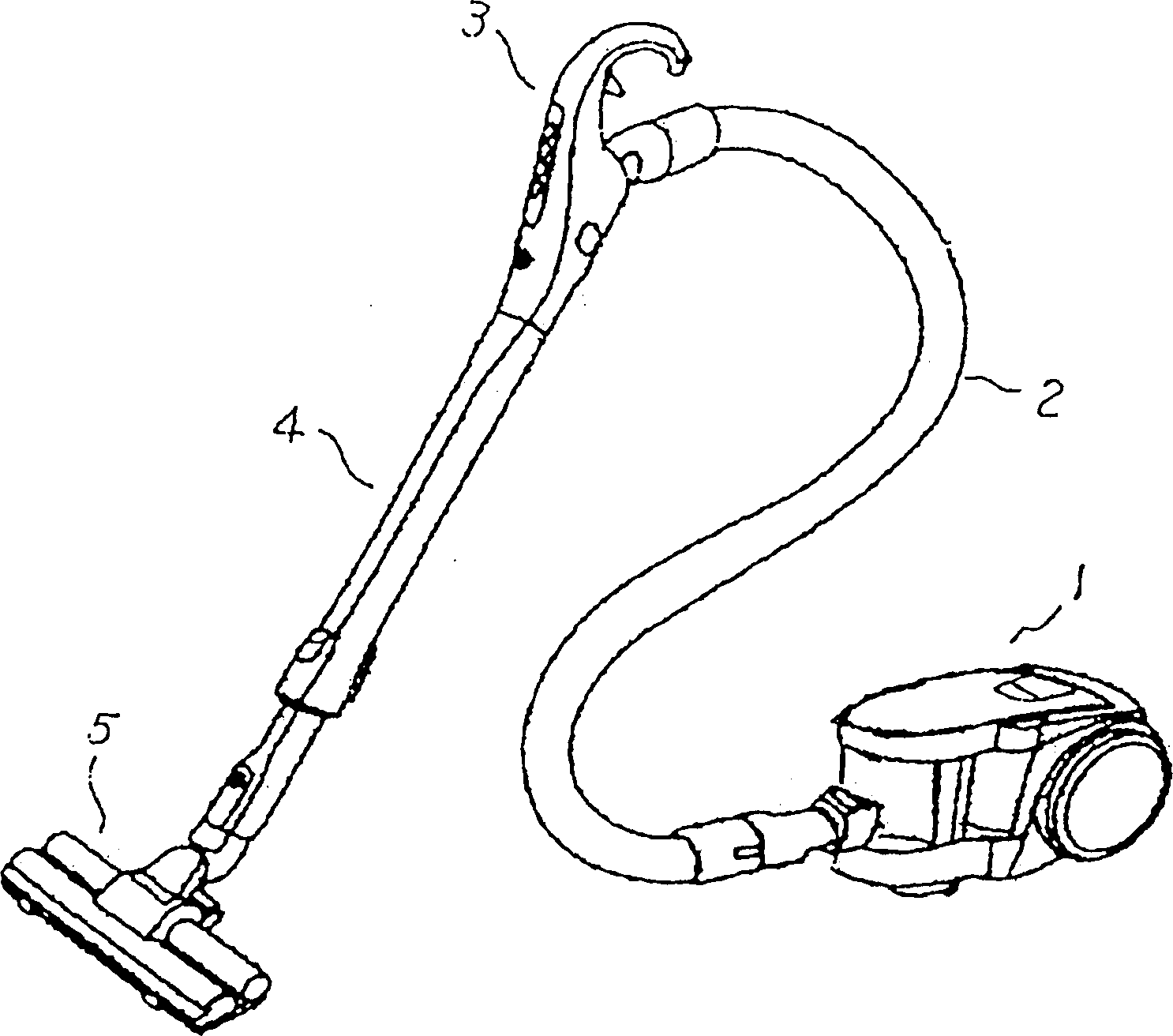
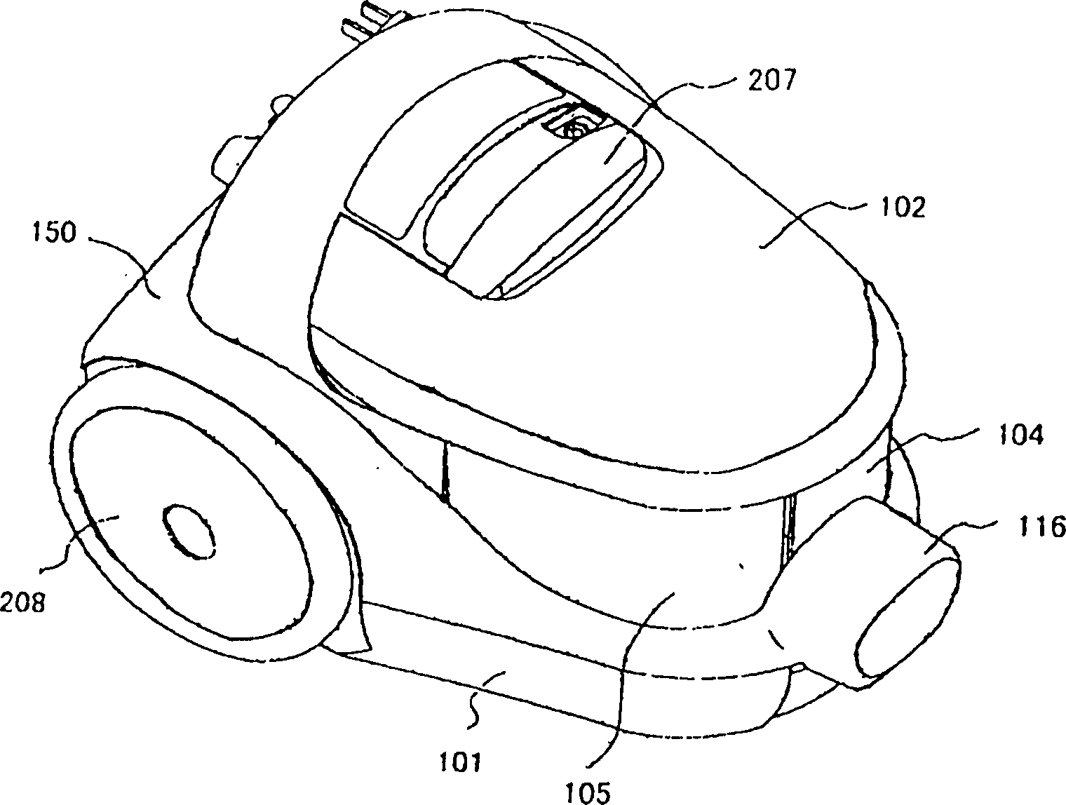
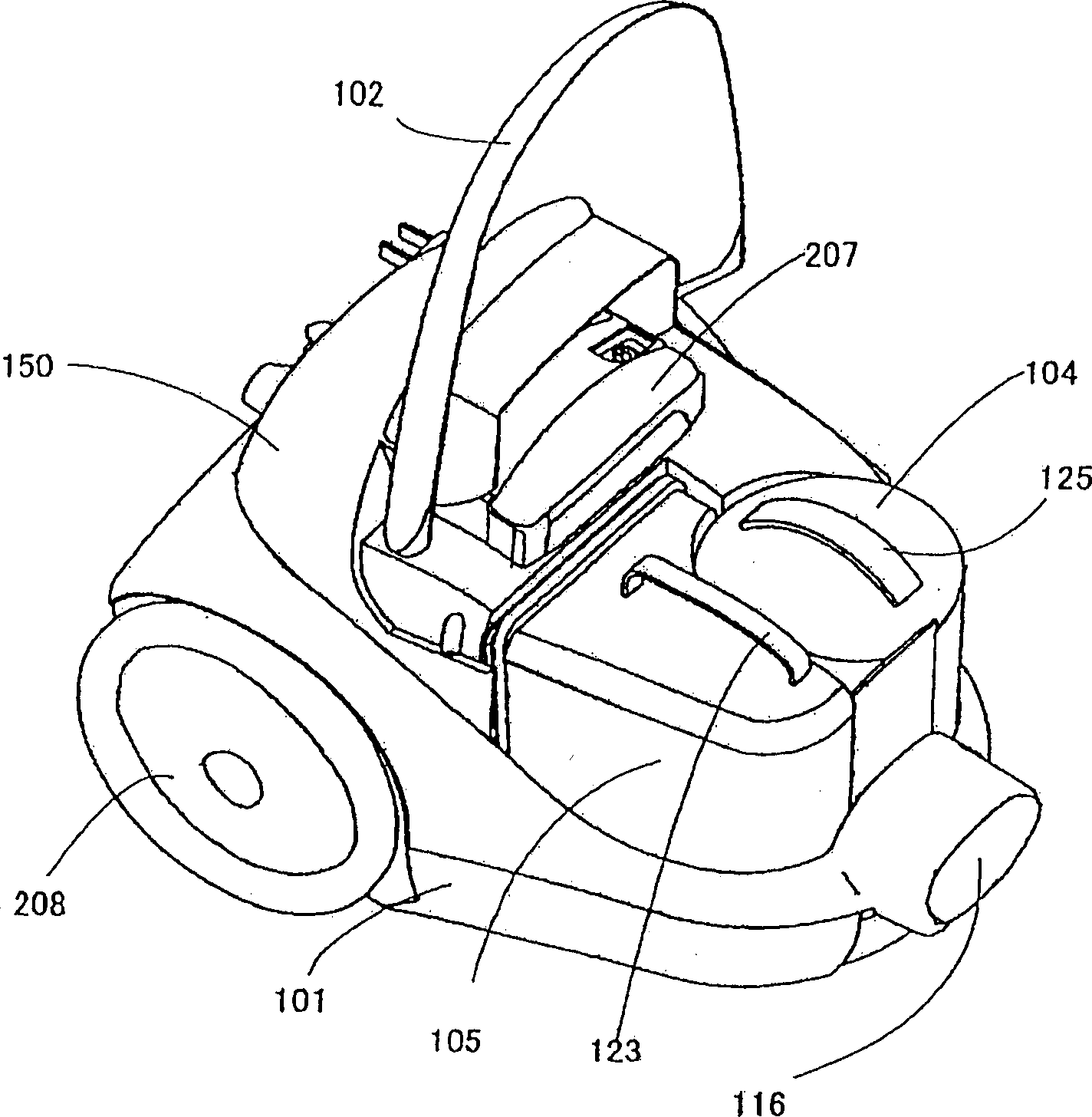
[0041] Embodiments of the present invention will be described below with reference to the drawings. figure 1 Shown is a perspective view of the appearance of an electric vacuum cleaner according to an embodiment of the present invention. figure 2 It is a perspective view of the vacuum cleaner body. image 3 Shown is a perspective view of the upper cover of the vacuum cleaner body in an open state. Figure 4 Shown is a perspective view of the dust collection box of the vacuum cleaner body in a state of being taken out. Figure 5 Shown is a perspective view of the dust collecting box and the cyclone separating cylinder of the electric vacuum cleaner in a state of being taken out. Figure 6 In order to take out the plan view of the upper cover and the upper case. Figure 7 It is a schematic diagram showing the air flow in the main body of the vacuum cleaner.
[0042] The electric vacuum cleaner in the present embodiment is as figure 1 As shown, a vacuum cleaner body 1, a ho...
Embodiment 2
[0078] use below Figure 7 (b), Figure 8 , Figure 9 , Figure 10 , Figure 11 (b), Figure 12 (b), Figure 13 (b), Figure 15 and Figure 16 A second embodiment of the present invention will be described.
[0079] Such as Figure 7 As shown in (b), in the vacuum cleaner body 1, the dust-laden air flows into the cyclone separation cylinder 104 through the hose 2 from the inlet pipe 115, and the dust is separated by the whirling centrifugal separation, and the dust is transported to the dust collection through the communication port 117 on the upper part. Box 105. The exhaust gas from the cyclone tube 104 passes through the inner tube 131 and is discharged to the exhaust port 120 provided at the lower part of the cyclone tube 104 . In addition, a part of the air flows into the dust box 105 and passes through the first auxiliary filter 106 to capture dust. The exhaust from the dust box 105 starts from the cyclone outlet 146 behind the first auxiliary filter 106 , pas...
Embodiment 3
[0120] Use below Figure 15 to Figure 18 A third embodiment of the present invention will be described. Figure 15 It is a perspective view showing the appearance of an upright electric vacuum cleaner according to an embodiment of the present invention. Figure 16 for Figure 15 Side view of the electric vacuum cleaner shown. Here, in order to explain the flow of air, a cross section is partially shown. Figure 17 It is a vertical sectional view when the cyclone separation cylinder 404 and the dust box 405 are integrated. Figure 18 It is a sectional view including the communication port 417 between the cyclone separation cylinder 404 and the dust collection box 405 .
[0121] In the vacuum cleaner body 301 , the suction port 305 opening toward the ground is installed to be rotatable within a certain angle range, and the suction port 305 is provided with a brush 306 which rotates facing the ground. The dust collecting unit 460 is detachably attached to the cleaner body 30...
PUM
 Abstract
Description
Claims
Application Information
 - R&D Engineer
- R&D Manager
- IP Professional
- Industry Leading Data Capabilities
- Powerful AI technology
- Patent DNA Extraction
Browse by: Latest US Patents, China's latest patents, Technical Efficacy Thesaurus, Application Domain, Technology Topic, Popular Technical Reports.
© 2024 PatSnap. All rights reserved.Legal|Privacy policy|Modern Slavery Act Transparency Statement|Sitemap|About US| Contact US: help@patsnap.com


