

Robot arm with wire traveling central hole
A robot arm, center hole technology, applied in the direction of claw arms, manipulators, manufacturing tools, etc., can solve problems such as wire breakage and winding
- Summary
- Abstract
- Description
- Claims
- Application Information
AI Technical Summary
Problems solved by technology
Method used
Image

Examples
specific Embodiment approach 1
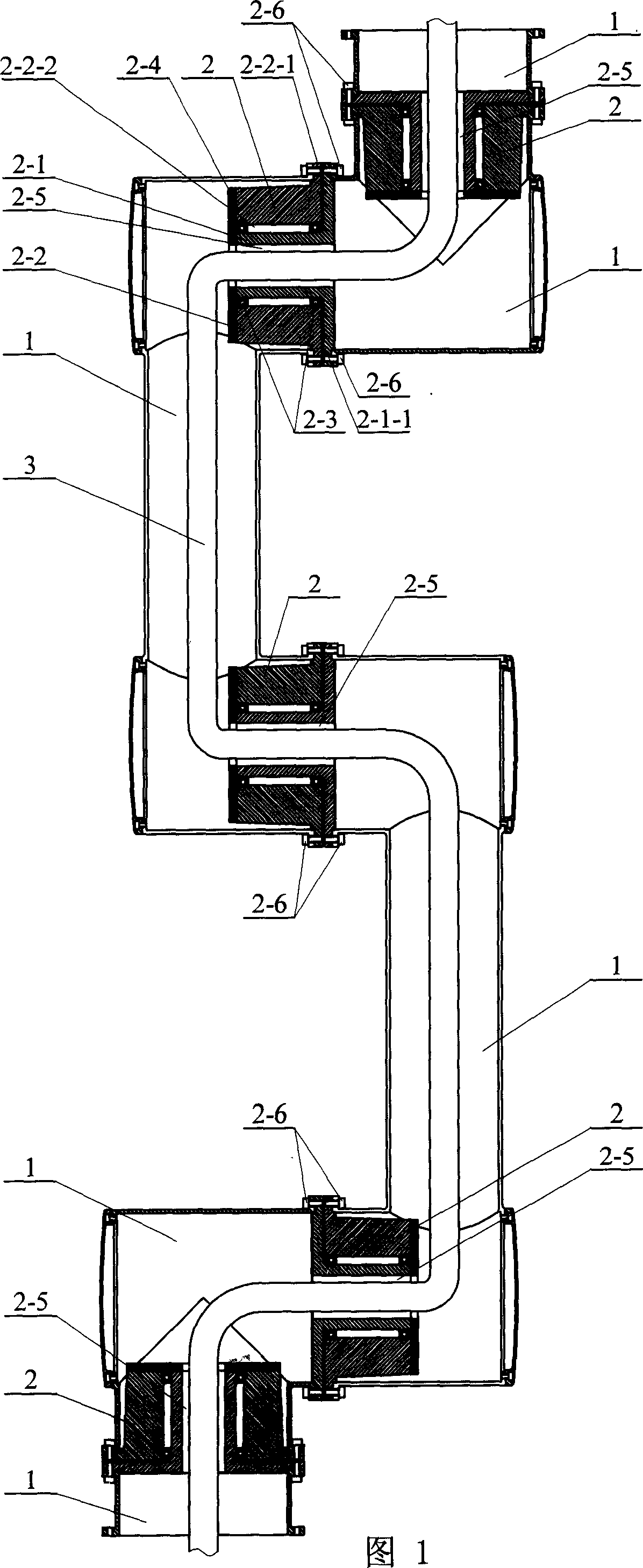
[0005] Specific embodiment one: (see Fig. 1) this embodiment comprises hollow arm 1 and joint 2, and the two connection ends of joint 2 are fixedly connected with the ends of every two adjacent hollow arm 1 respectively, and described joint 2 has wiring hole 2-5 in it.
specific Embodiment approach 2
[0006] Specific embodiment 2: (see Fig. 1) The difference between this embodiment and specific embodiment 1 is that the joint 2 includes an inner connector 2-1, an outer connector 2-2, a bearing 2-3, and a baffle 2- 4 and bolts 2-6, the outer connector 2-2 has an axial through hole 2-2-2, one end of the outer connector 2-2 is fixed with a No. 2 flange 2-2-1, and the baffle plate 2- 4 It is fixedly connected with the end face of the other end of the outer connector 2-2; one end of the inner connector 2-1 is fixed with a No. 1 flange 2-1-1, and the other end of the inner connector 2-1 is inserted into the outer connector 2 -2 in the axial through hole 2-2-2 and the bearing 2-3 is placed between the inner connector 2-1 and the outer connector 2-2, the inner connector 2-1 of the joint 2 and the baffle plate 2- 4 has wiring holes 2-5; the two ends of the hollow arm 1 are fixed with arm flanges, and the No. 1 flange 2-1-1 and the No. 2 flange 2-2-1 of the joint 2 are There are inte...
PUM
 Abstract
Description
Claims
Application Information