Rotary compressor, method for manufacturing the same, and defroster for refrigerant circuit

A rotary compressor, compression technology, applied in the direction of compressors, irreversible cycle compressors, machines/engines, etc., can solve the problems of unstable operation of the second rotary compression unit

Inactive Publication Date: 2006-07-26
SANYO ELECTRIC CO LTD
View PDF0 Cites 2 Cited by
  • Summary
  • Abstract
  • Description
  • Claims
  • Application Information

AI Technical Summary

Problems solved by technology

[0026] However, in this case, the discharge side of the first rotary compression unit communicates with the discharge side of the second rotary compression unit, so that the suction side and the discharge side of the second rotary compression unit are at the same pressure, so there is a second rotary compression unit. Unstable operation of the 2nd rotary compression unit such as blade jumping of the compression unit

Method used


Image

  • Rotary compressor, method for manufacturing the same, and defroster for refrigerant circuit
  • Rotary compressor, method for manufacturing the same, and defroster for refrigerant circuit
  • Rotary compressor, method for manufacturing the same, and defroster for refrigerant circuit

Examples


Embodiment Construction

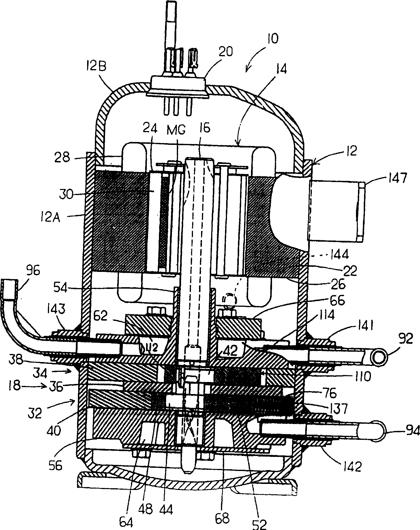
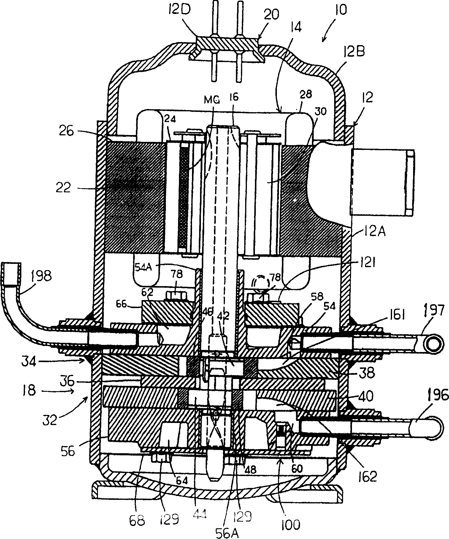
[0074] Hereinafter, embodiments of the present invention will be described in detail with reference to the drawings. figure 1 A longitudinal sectional view of an internal intermediate pressure type multi-stage (two-stage) compression rotary compressor 10 having first and second rotary compression units 32 and 34 is shown as an embodiment of the rotary compressor of the present invention.

[0075] In this figure, symbol 10 is carbon dioxide (CO 2 ) is an internal intermediate pressure type multi-stage compression rotary compressor used as a refrigerant. The rotary compressor 10 is composed of a cylindrical airtight container 12 made of steel plates, an electric unit 14, and a rotary compression mechanism part 18. The electric unit 14 Arranged and accommodated on the upper side of the inner space of the airtight container 12, the rotary compression mechanism part 18 includes a first rotary compression unit 32 (first stage) disposed on the lower side of the electric unit 14 and ...


PUM


Abstract

The invention provides a rotary compressor used to structurally simplify a laminae which divides a cylinder into a low-pressure chamber and a high-pressure chamber; in addition, the invention provides a multi-stage rotary compressor, the manufacturing method thereof and a defrosting device used in a coolant loop. The rotary compressor(10)comprises a first and a second rotary compressing units(32,34) which are driven via an electromotor(14) arranged in a sealed container(12). The first rotary compressing unit(32)is composed of an upper cylinder(38), a swinging piston(110) for a roller(112)which is connected with an eccentric unit(42)on the rotary shaft(16)of the electromotor(14) and eccentrically moves inside the upper cylinder(38), and a laminae(114) which is molded on the swinging piston(110) and protrudes in the radial direction from the roller(112)to divide the upper cylinder(38)into a low-pressure chamber and a high-pressure chamber. A retaining member is arranged to retain the laminae(114) of the swinging piston(110)in a sliding and swingy mode.

Description

[0001] This application is a divisional application of the patent application filed on August 28, 2002 with the title of "rotary compressor, its manufacturing method, and a box removal device using the compressor" and application number 02142300.8. technical field [0002] The present invention relates to an airtight container with an electric unit and a rotary compression unit driven by the electric unit for CO 2 A rotary compressor that compresses the refrigerant. [0003] The present invention also relates to a multi-stage compression type rotary compressor that sucks refrigerant gas compressed and discharged by the first rotary compression unit to the second rotary compression unit, compresses it, and discharges it, a manufacturing method thereof, and a compressor using the same. The defrosting device of the refrigerant circuit of the machine. Background technique [0004] A conventional internal intermediate pressure type multi-stage compression type rotary compressor ...

Claims


Application Information

Patent Timeline
Patent Type & Authority Applications(China)
IPC IPC(8): F04C18/356F04C23/00F25B1/10F25B9/00
CPCF04C23/001F04C23/008F04C18/3564
Inventor 松本兼三山崎晴久只野昌也里和哉松浦大斋藤隆泰津田德行
Owner SANYO ELECTRIC CO LTD
Why Eureka
Try Eureka