Supercharge Your Innovation With Domain-Expert AI Agents!

Light emitting apparatus

A light-emitting device, a technology of light-emitting diodes, applied in lighting and heating equipment, optics, light sources, etc., can solve problems such as a large number of resistances and troubles

Active Publication Date: 2006-07-26
CITIZEN ELECTRONICS CO LTD
View PDF0 Cites 10 Cited by
  • Summary
  • Abstract
  • Description
  • Claims
  • Application Information

AI Technical Summary

Problems solved by technology

[0017] Alternatively, in a light emitting device that realizes an increase in the amount of light by connecting a plurality of LED chips in parallel, there is such a trouble that the current limiting resistors 501a, 501b, 501c...501n must be connected to each of the LED chips 502a, 502b, 502c...502n, respectively. problem, which requires a large resistor

Method used


Image

  • Light emitting apparatus
  • Light emitting apparatus
  • Light emitting apparatus

Examples


Embodiment Construction

[0028] Preferred embodiments of the present invention will be described in detail below with reference to the accompanying drawings.

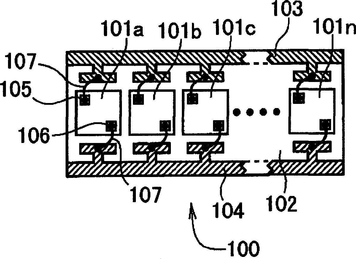
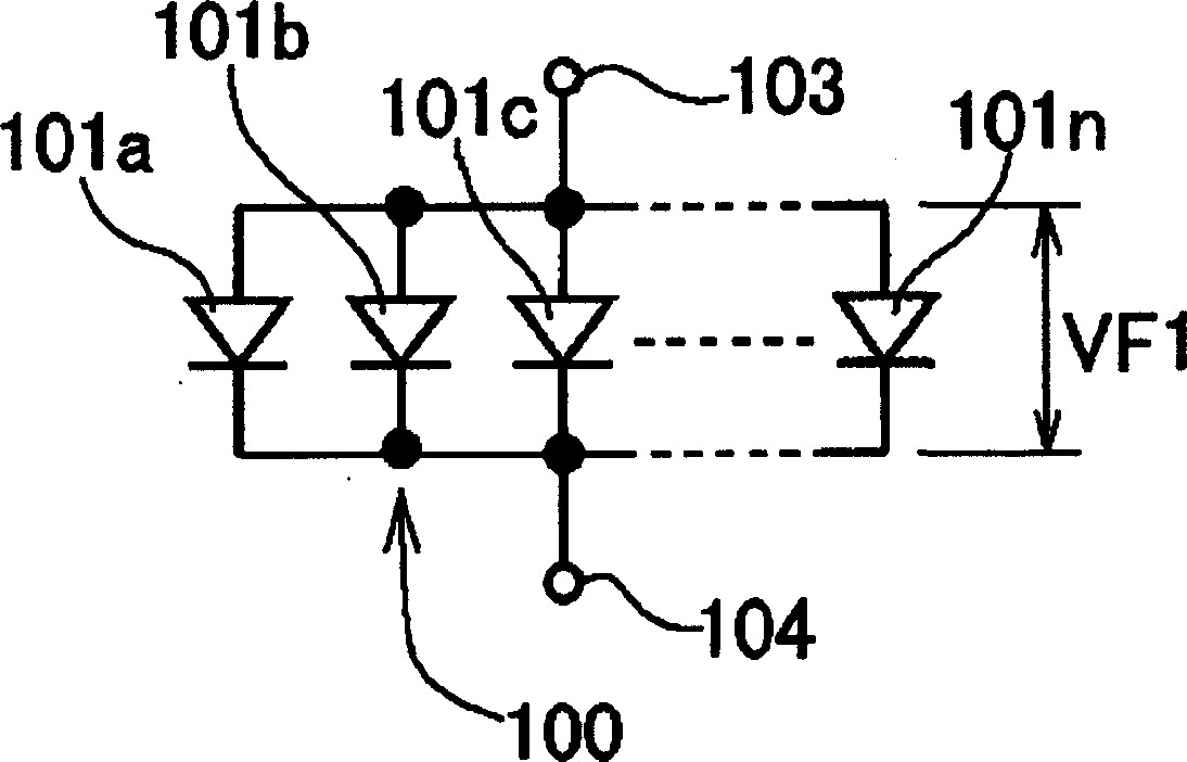
[0029] figure 1 and 2 A light emitting device according to a first embodiment of the present invention is shown. The lighting device includes a figure 1 and 2 The diode assembly 100 is shown. The diode assembly 100 has a substrate 102 and a plurality of LED chips 101a, 101b, 101c... 101n mounted on the substrate 102 (see figure 1 ). The LED chips 101a, 101b, 101c... 101n are connected in parallel to the anode-side common electrode 103 and the cathode-side common electrode 104 (see figure 2 ).

[0030] In more detail, each LED chip 101a, 101b, 101c... 101n has an anode 105 connected to the common electrode 103 on the anode side and a cathode 106 connected to the electrode 104 on the cathode side through bonding wires 107 respectively (see figure 1 ). Of course, in addition to using bonding wires 107 , bumps can also be used for electri...


PUM


Abstract

The present invention provides a light emitting apparatus including one diode package, the diode package including a plurality of LED chips connected in parallel with an anode side common electrode and a cathode side common electrode, the plurality of LED chips being set so that a voltage is applied to each of the LED chips in a forward direction.

Description

technical field [0001] The present invention relates to a light emitting device using a light emitting diode (LED) chip, and more particularly to a light emitting device mainly used for a flashlight of a compact camera or the like. Background technique [0002] In recent years, high-capacity LEDs have been developed that can emit uniform and intense light for use in liquid crystal displays, and especially high-capacity colorless power diodes have begun to be used in flashlights for compact cameras, etc. since they show no change in color . [0003] When forming a high-capacity power diode, the amount of light emitted from a single LED chip is not enough, and an increase in the amount of light is usually achieved by using multiple LED chips. [0004] An increase in the amount of light brought about by using a plurality of LED chips as a light emitting device can be realized by using a structure in which LED chips are connected in parallel and a structure in which LED chips a...

Claims


Application Information

Patent Timeline
Patent Type & Authority Applications(China)
IPC IPC(8): F21S4/00F21V23/00G03B15/05G02F1/13357F21Y101/02F21K9/238F21Y115/10G02F1/1335
Inventor 石坂光识石井广彦
Owner CITIZEN ELECTRONICS CO LTD
Features
  • R&D
  • Intellectual Property
  • Life Sciences
  • Materials
  • Tech Scout
  • Unparalleled Data Quality
  • Higher Quality Content
  • 60% Fewer Hallucinations
Learn More