Display module

A technology for display modules and display panels, which is applied in the direction of electrical equipment structural parts, reversing machines, other manufacturing equipment/tools, etc., can solve the problem that heat cannot be properly dissipated, uncomfortable, and damages the circuit devices of the driving circuit board 40. And other issues

Inactive Publication Date: 2006-07-26
SAMSUNG SDI CO LTD
View PDF1 Cites 6 Cited by
  • Summary
  • Abstract
  • Description
  • Claims
  • Application Information

AI Technical Summary

Problems solved by technology

[0007] In particular, when the heat generated during operation cannot be properly dissipated, the circuit components of the driving circuit board

Method used


Image

  • Display module
  • Display module
  • Display module

Examples


Embodiment Construction

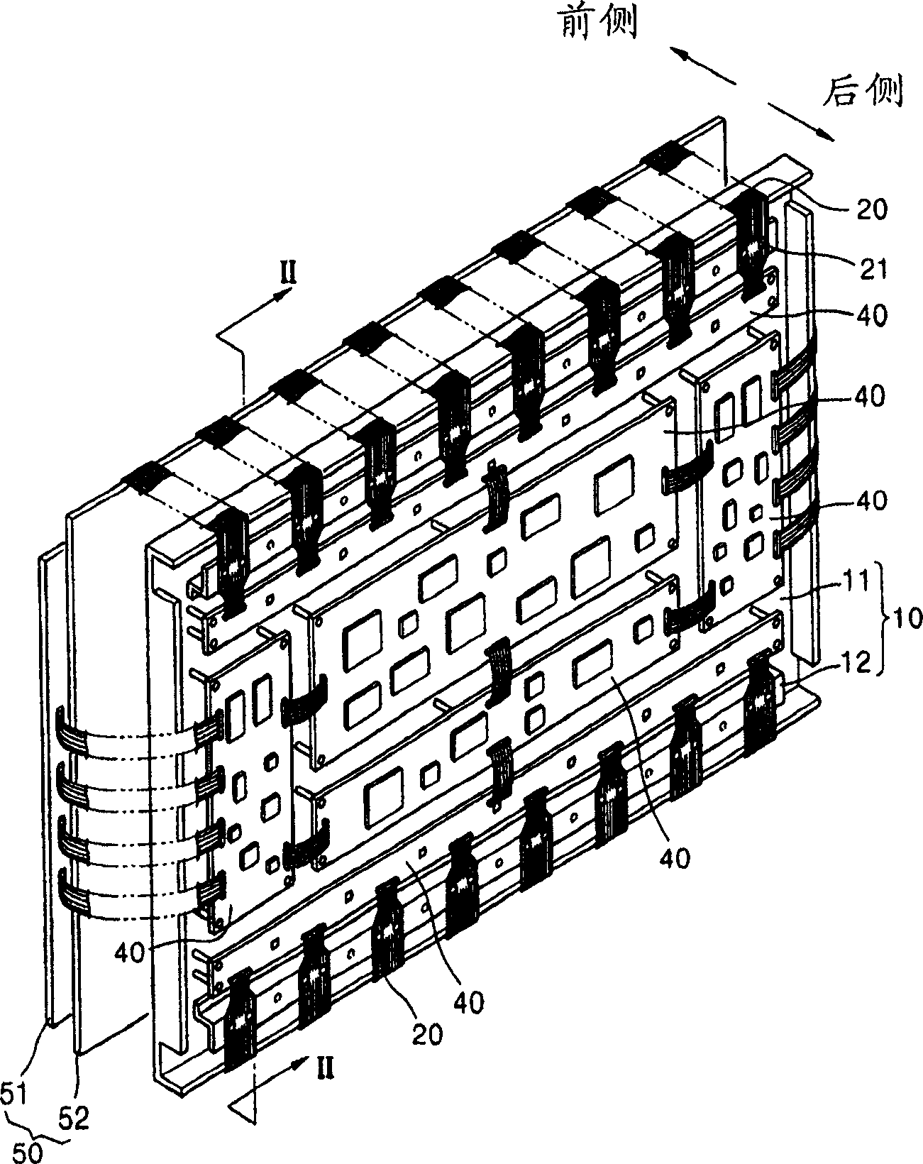
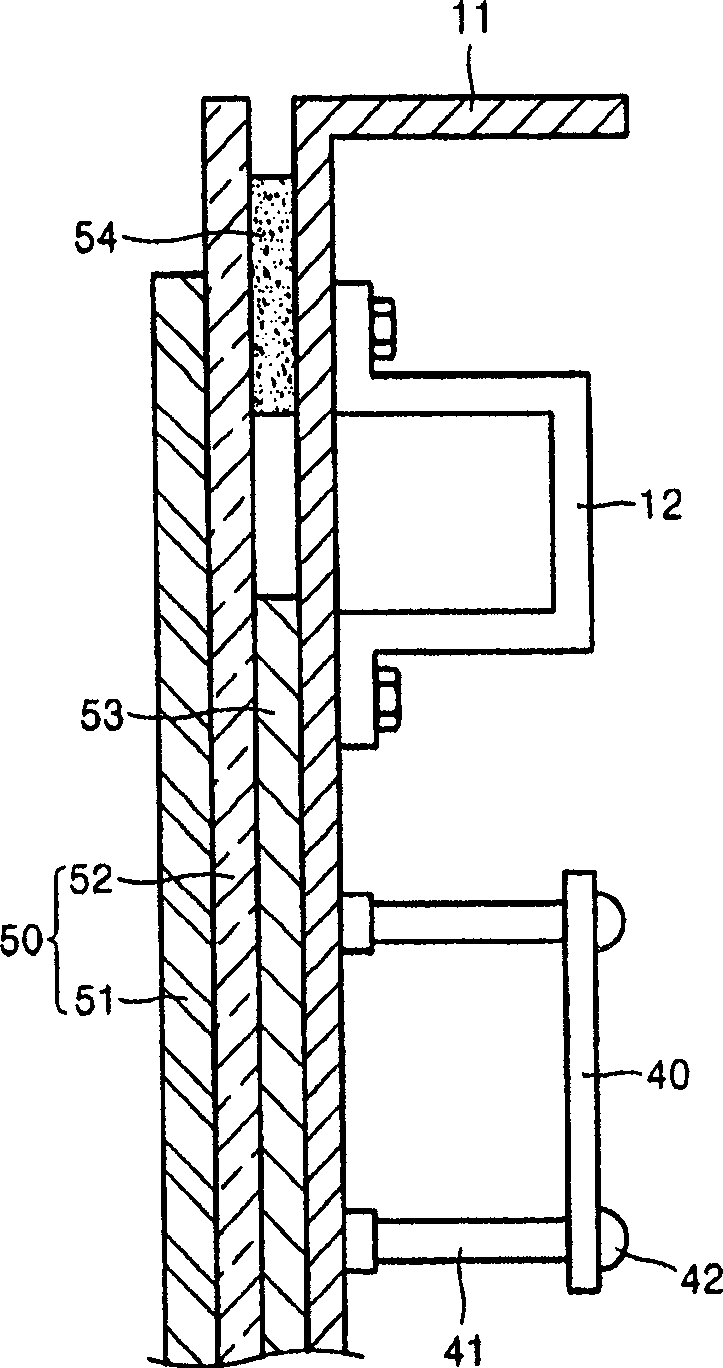
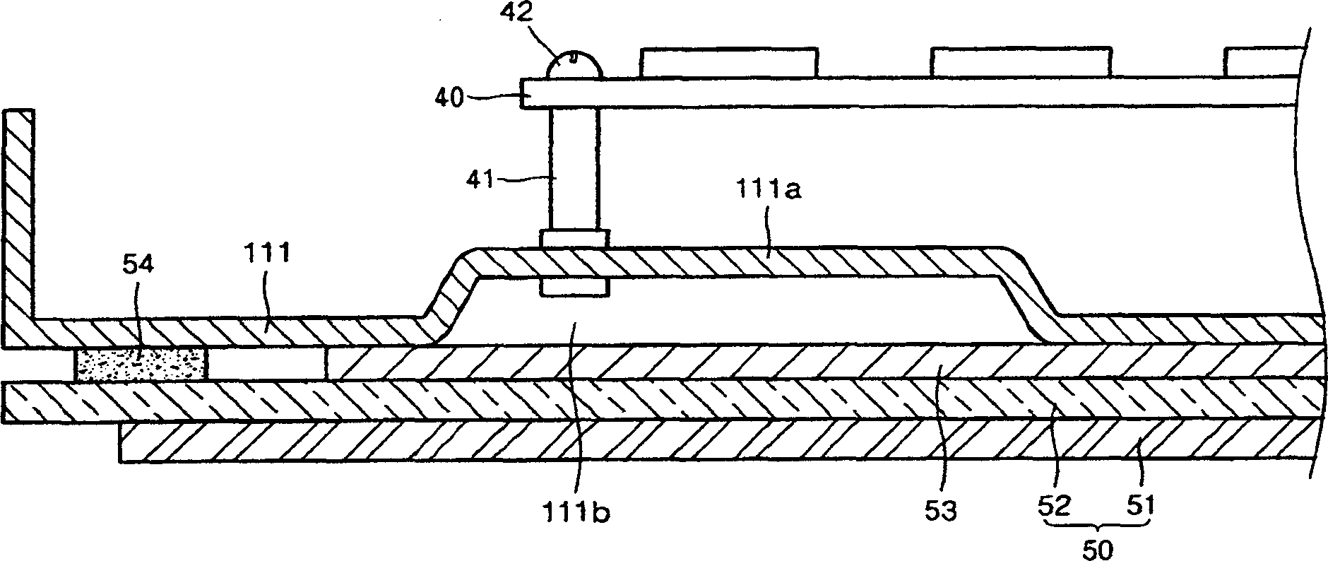
[0022] image 3 is a cross-sectional view showing the structure of a display module according to an embodiment of the present invention. refer to image 3 , the display module includes a display panel 50 , a driving circuit board 40 and a bottom plate 111 .

[0023] In one embodiment, the display panel 50 may be a plasma display panel including a front panel 51 and a rear panel 52 coupled to each other. In another embodiment, the display panel 50 may be another flat panel display supported by a panel support structure. In one embodiment, such as image 3 As shown, rear panel 52 is secured to chassis 111 using, for example, double-sided adhesive tape 54 .

[0024] The driving circuit board 40 including a plurality of circuit devices for driving the display panel 50 may be a typical printed circuit board. In one embodiment, such as image 3 As shown, the driving circuit board 40 is fixed to the rear surface of the bottom plate 111 by means of a boss 41 mounted on the bottom pl...


PUM


Abstract

A display module, used for, e.g., a plasma display panel, is disclosed. In one embodiment, the display module includes a display panel, a drive circuit board driving the display panel, and a chassis base supporting the display panel and the drive circuit board. A curved portion is formed on the chassis base with a predetermined width, a boss is installed on an upper surface of the curved portion, and the drive circuit board is installed on the top of the boss. According to embodiments of the present invention, the strength of the chassis base constituting the display module is reinforced, without requiring a separate reinforcement member, and simultaneously the heat and noise generated by the display panel and the drive circuit board during operation can be appropriately dissipated and prevented.

Description

[0001] Cross references to related patent applications [0002] This application claims the benefit of Korean Patent Application No. 10-2005-0005382 filed in the Korean Intellectual Property Office on Jan. 20, 2005, the disclosure of which is incorporated herein by reference in its entirety. technical field [0003] The present invention relates to a display module which may be used in a plasma display panel device or other flat panel display devices, and more particularly, to a display module having enhanced strength and improved heat dissipation and noise reduction characteristics. Background technique [0004] FIG. 1 is a perspective view of a display module of a plasma display as an example to explain the structure of a display module according to the related art. FIG. 2 is a cross-sectional view along line II-II of FIG. 1 . Referring to FIGS. 1 and 2, the display module includes a display panel 50 having a front panel 51 and a rear panel 52, a plurality of driving circ...

Claims


Application Information

Patent Timeline
IPC IPC(8): G09F9/00G09F9/313H05K7/02H05K7/20
CPCG06F1/1601H05K7/20963D02H5/02D02H13/00D06B15/00
Inventor 金明坤
Owner SAMSUNG SDI CO LTD
Why Eureka
Try Eureka