Device for cleaning the fire tubes in a boiler

A technology for fire tubes and boilers, which is applied in the direction of cleaning heat transfer devices, removing solid residues, cleaning non-rotating equipment, etc., and can solve problems such as not being able to reapply

Active Publication Date: 2006-07-26
OPTIMUM ENVIRONMENTAL & ENERGY TECH BV
View PDF2 Cites 8 Cited by
  • Summary
  • Abstract
  • Description
  • Claims
  • Application Information

AI Technical Summary

Problems solved by technology

If kinking occurs, the force required to push the brush through the fire tube can no longer be applied

Method used


Image

  • Device for cleaning the fire tubes in a boiler
  • Device for cleaning the fire tubes in a boiler
  • Device for cleaning the fire tubes in a boiler

Examples


Embodiment Construction

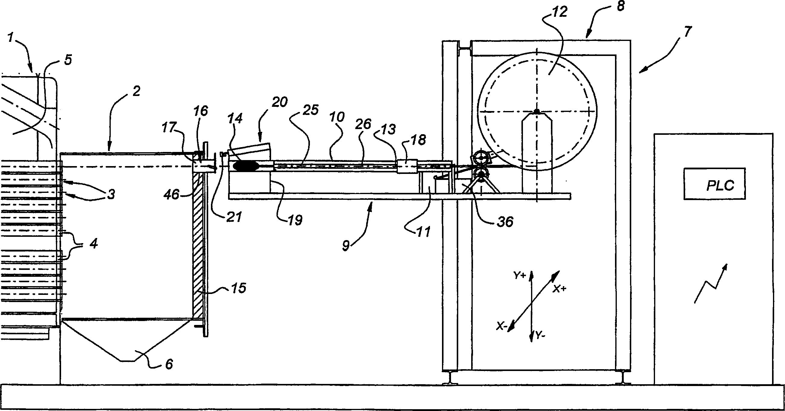
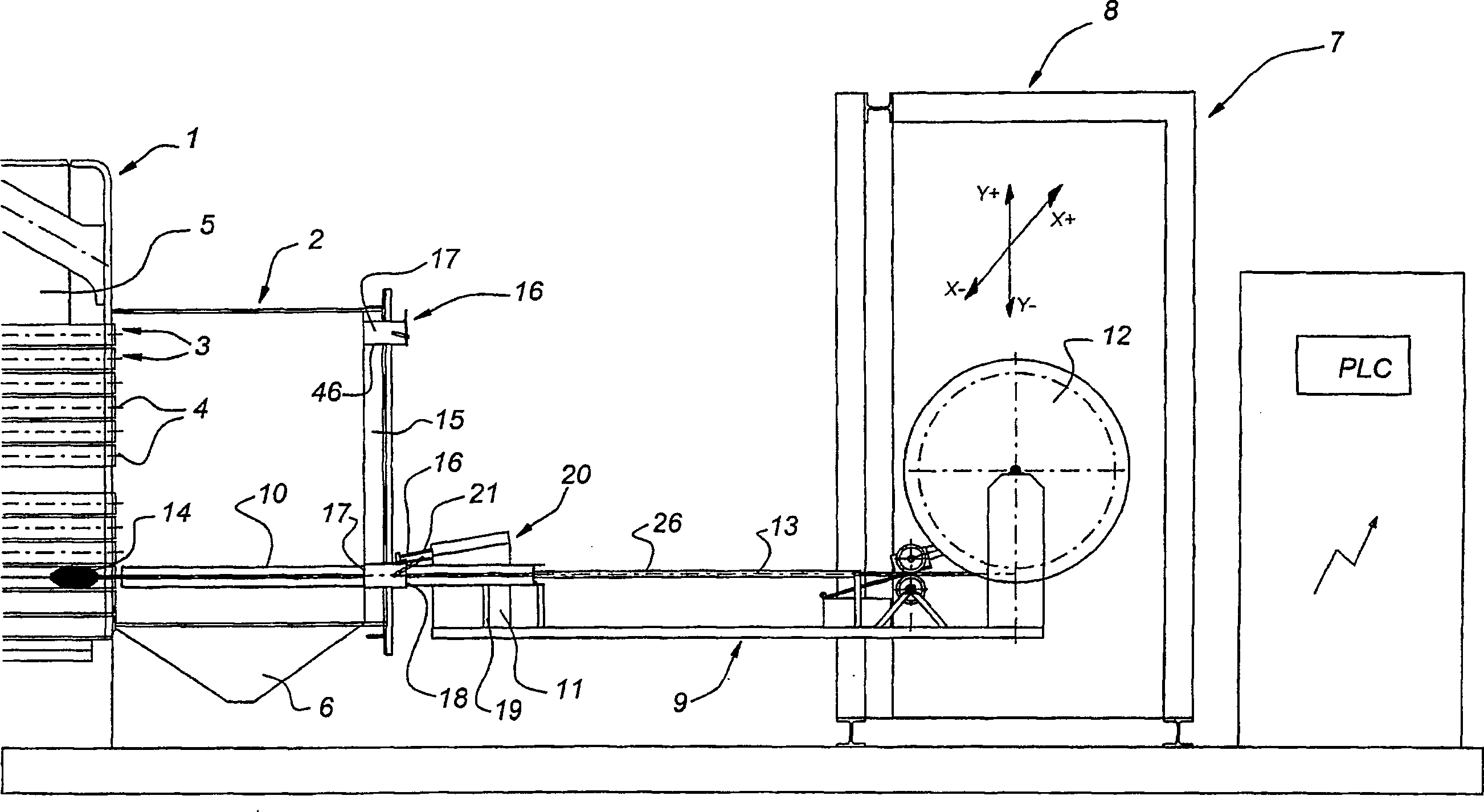
[0034] figure 1 with 2 The end of the boiler 1 is shown where the flue chamber 2 is arranged. In conventional manner, the boiler 1 has a number of fire tubes 3 , the ends 4 of which open into the flue chamber 2 as shown. At the other end, not shown, there is a burner which produces hot flue gases which flow through the fire tube 3 . The water outside the fire tubes 3 of the chamber 5 in the boiler 1 can be heated with these hot flue gases.

[0035]The flue gases that have flowed through the fire tube 3 can be collected in the flue chamber 2 . The flue chamber 2 is delimited at the bottom by a collection device 6 , in which wastes arising from the combustion process as well as wastes settled inside the fire tube 3 can be collected. These deposits are mainly dependent on the fuel used in the burner. Combustion of gases produces relatively little fouling; solid fuels, on the other hand, produce more fouling deposits in the fire tube.

[0036] Adjacent to the flue chamber 2 ...


PUM


Abstract

A device for use when cleaning the heating surface of a tube changer, such as the fire tubes (3) in a boiler (1), comprises a scraper member (14) that is fixed to a movement member (13) for moving said scraper member (14) though one fire tube (3) at a time and a guide (10) for positioning the scraper member (14) directly in front of the open end (4) of a fire (tube3), such that said scraper member (14) can be moved from the guide (10) into the fire tube (3) and conversely from the fire tube (3) into the guide (10). The guide (10) can be moved on a frame (8) transversely with respect to the longitudinal direction of the fire tubes (3) for automatic cleaning of the fire tubes (3) both when in service and out of service.

Description

technical field [0001] The invention relates to a combination of a boiler with fire tubes and a device for cleaning the fire tubes in the boiler, said device for cleaning the fire tubes in the boiler comprising a scraper member fixed to the The scraper member is moved through a moving member of the fire tube at a time, and a guide for positioning the scraper member directly in front of the open end of the fire tube so that the scraper member can move from the guide to the fire tube. In the tube and conversely from the fire tube into the guide, in boilers with fire tubes, the fire tube is open at one end of the boiler, wherein the guide is movable on the frame transversely with respect to the longitudinal direction of the fire tube, the machine A rack is arranged at the boiler end where the fire tubes are open, and a flue chamber is arranged at the boiler end where the fire tubes are open, the flue chamber having a plurality of apertures each arranged opposite the fire tubes. ...

Claims


Application Information

Patent Timeline
Patent Type & Authority Applications(China)
IPC IPC(8): F28G1/08F23J3/02F28G15/02F28G15/04
CPCF23J3/023F28G1/08F28G15/04F28G15/02
Inventor 尼尔斯·亚历山大·罗森达尔
Owner OPTIMUM ENVIRONMENTAL & ENERGY TECH BV
Why Eureka
Try Eureka