Hydraulic pipe clamp

A hydraulic and pipe technology, which is applied in the direction of manufacturing tools, workpiece clamping devices, workbenches, etc., can solve the problems of inconvenient use and cumbersome operation, and achieve the effect of easy clamping, simple operation, and not easy to slip

Inactive Publication Date: 2022-04-22
XUZHOU COLLEGE OF INDAL TECH
View PDF0 Cites 2 Cited by
  • Summary
  • Abstract
  • Description
  • Claims
  • Application Information

AI Technical Summary

Problems solved by technology

[0004] The invention provides a hydraulic clamp for pipes, which is convenient for fixing pipes of different diameters, facilitates the movement of the device body, and has the beneficial effects of simple operation, and solves the need for multiple sets of bolts in the traditional clamping device mentioned in the background technology Reverse, the operation is more cumbersome and inconvenient to use

Method used


Image

  • Hydraulic pipe clamp
  • Hydraulic pipe clamp
  • Hydraulic pipe clamp

Examples


Embodiment 1

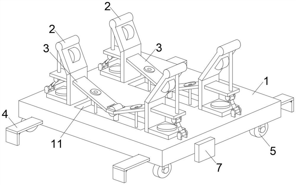
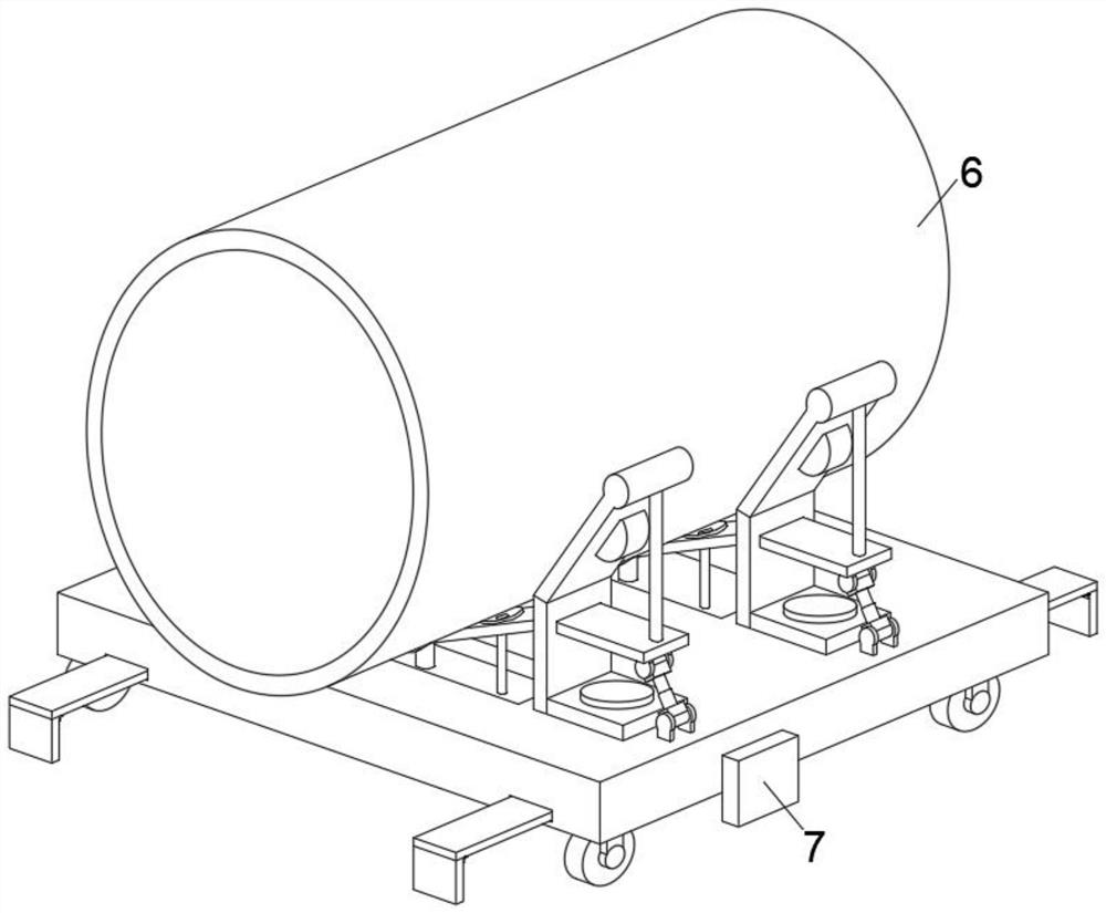
[0029] This embodiment is intended to promote the solution to the problem of how to clamp the pipe body 6, please refer to Figure 1-5 , a hydraulic clamp for pipes, comprising a stable base 1, a universal sliding wheel 5 is installed on the lower end of the stable base 1, by installing the universal sliding wheel 5, it is convenient to drag the stable base 1 to move around, and one end of the stable base 1 is fixed A control panel 7 is installed, and the operation of the whole device can be controlled through the control panel 7. The side clamping mechanism 2 is installed on the stable base 1, and the side clamping mechanism 2 is provided with two groups. On both sides of the base 1, a bottom clamping mechanism 3 is interspersed between the two groups of side clamping mechanisms 2, and the bottom clamping mechanism 3 is arranged on the inclined bottom plate 31 between the two groups of side clamping mechanisms 2 and is fixedly installed on the inclined bottom plate. 31 outsid...

Embodiment 2

[0040] This embodiment is intended to help solve the problem of how to clamp pipe bodies 6 of different diameters. This embodiment is an improvement made on the basis of Embodiment 1. For details, please refer to Figure 4-6 , the side clamping mechanism 2 includes a stable bottom plate 21 fixedly mounted on the stable base 1 and an elastic vertical plate 22 fixedly mounted on the stable bottom plate 21, the stable bottom plate 21 is interspersed with bolts 8, and the bolts 8 are threadedly connected with the stable base 1 , to facilitate the fixing of the stable base plate 21, the elastic vertical plate 22 is equipped with an elastic inclined plate 23, and the elastic vertical plate 22 is provided with an opening groove 25, and the opening groove 25 is inserted and connected with the adjustment push plate 32.

[0041] The angle between the inclined bottom plate 31 and the adjustment push plate 32 is fixed, so the opening slot 25 can be used as a fulcrum to swing up and down, s...

Embodiment 3

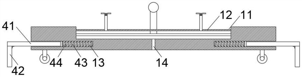
[0046] This embodiment is intended to promote the solution of how to securely fix the device on operating platforms of different lengths. This embodiment is an improvement made on the basis of Embodiment 1. For details, please refer to Figure 1-3 , a mounting mechanism 4 is installed on the stable base 1, and the mounting mechanism 4 includes a transverse connecting plate 41 inserted in the built-in hole 13 and a vertical limit plate 42 hinged at the lower end of the transverse connecting plate 41 through a damping shaft. A slide bar 43 is interspersed and connected, and the slide bar 43 is fixedly installed in the built-in hole 13 .

[0047] The installation mechanism 4 is provided with four groups, and the four groups of installation mechanisms 4 are installed on the two ends of the stable base 1 correspondingly. The horizontal connecting plate 41 fits together to avoid the movement of the vertical limiting plate 42 when the stable base 1 is moving. After the installation o...


PUM


Abstract

The invention relates to the technical field of pipe machining, and discloses a hydraulic pipe clamp which comprises a stable base, side clamping mechanisms are installed on the stable base, and a bottom clamping mechanism is inserted between the two side clamping mechanisms in a penetrating mode. The bottom clamping mechanism comprises an inclined bottom plate arranged between the two side clamping mechanisms and an adjusting push plate fixedly installed on the outer side of the inclined bottom plate, a connecting supporting rod is installed on the adjusting push plate, a telescopic hydraulic rod is movably installed at the lower end of the adjusting push plate, and the telescopic hydraulic rod is movably installed on a stable base. When the telescopic hydraulic rods extend, the adjusting push plates are driven to move upwards, the center parts of the inclined bottom plates move downwards, then the distance between the two sets of inclined bottom plates is shortened, pipe bodies with small diameters can be conveniently placed, and on the contrary, when the telescopic hydraulic rods are shortened, the distance between the two sets of inclined bottom plates can be increased. And a pipe body with a large diameter can be conveniently clamped, and the clamping effect is good.

Description

technical field [0001] The invention relates to the technical field of pipe processing, in particular to a hydraulic pipe clamp. Background technique [0002] The hydraulic pipe is an important component of the hydraulic equipment, and the quality of the hydraulic pipe is one of the keys related to the normal performance of the hydraulic system. During the processing of hydraulic pipes, it is necessary to cut the hydraulic pipes into hydraulic pipe sections with different lengths to meet the actual production needs. In traditional hydraulic pipe cutting, the operator directly cuts the hydraulic pipes with a hand-held cutting machine, and the hydraulic pipes will be cut with the cutting machine. The machine shakes, which reduces the cutting accuracy of the hydraulic pipe. The fixture is a device used to fix the processing object in the mechanical manufacturing process so that it occupies the correct position for construction or inspection. [0003] In the process of pipe pro...

Claims


Application Information

Patent Timeline
Patent Type & Authority Applications(China)
IPC IPC(8): B25B11/00B25H1/10B25H5/00
CPCB25B11/005B25H1/10B25H5/00
Inventor 权宁钱博坤李建松朱涛纪海宾
Owner XUZHOU COLLEGE OF INDAL TECH
Why Eureka
Try Eureka