Elevator guide rail structure

A technology for elevator guide rails and elevators, which is applied to springs/shock absorbers, elevators, vibration suppression adjustment, etc., can solve the problems of falling off of the support plate, affecting the work efficiency of the staff, and poor fixing effect of the support plate, and achieves the effect of easy operation.

Inactive Publication Date: 2022-06-24
浙江有东电梯配件有限公司
View PDF0 Cites 0 Cited by
  • Summary
  • Abstract
  • Description
  • Claims
  • Application Information

AI Technical Summary

Problems solved by technology

[0006] The present invention provides an elevator guide rail structure, one purpose of which is to solve the problem that some elevator guide rail structures have poor shock absorption effects during operation, and the relatively large impact force may easily cause damage to the device, thereby seriously affecting the device. The problem of service life; another purpose is to solve the poor fixing effect of some elevator guide rail structure support plates, and it is easy to cause the support plate to fall off during the moving process, thus causing unnecessary damage and affecting the work of the staff efficiency problem

Method used


Image

  • Elevator guide rail structure
  • Elevator guide rail structure
  • Elevator guide rail structure

Examples


Embodiment 1

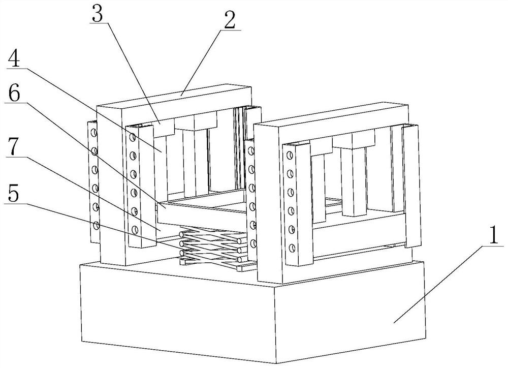
[0035] like Figure 1-6 As shown, the present invention provides an elevator guide rail structure, comprising a guide rail base 1, the upper end of the guide rail base 1 is fixedly connected with an elevator support 2, the lower end of the elevator support 2 is fixedly connected with a hydraulic cylinder 3, and the lower end of the hydraulic cylinder 3 is provided with a telescopic The lower end of the rod 4 and the telescopic rod 4 is fixedly connected with a support slide 7 .

[0036] The elevator bracket 2 , the hydraulic cylinder 3 , the telescopic rod 4 and the support slide plate 7 are arranged to facilitate the pulling of the support plate 6 , so as to make the elevator move and facilitate the operation of the staff.

[0037] The upper end of the guide rail base 1 is provided with a telescopic assembly 5, and the setting of the telescopic assembly 5 can support the lower end of the support plate 6, so as to avoid the large gravity of the upper end, causing the support s...

Embodiment 2

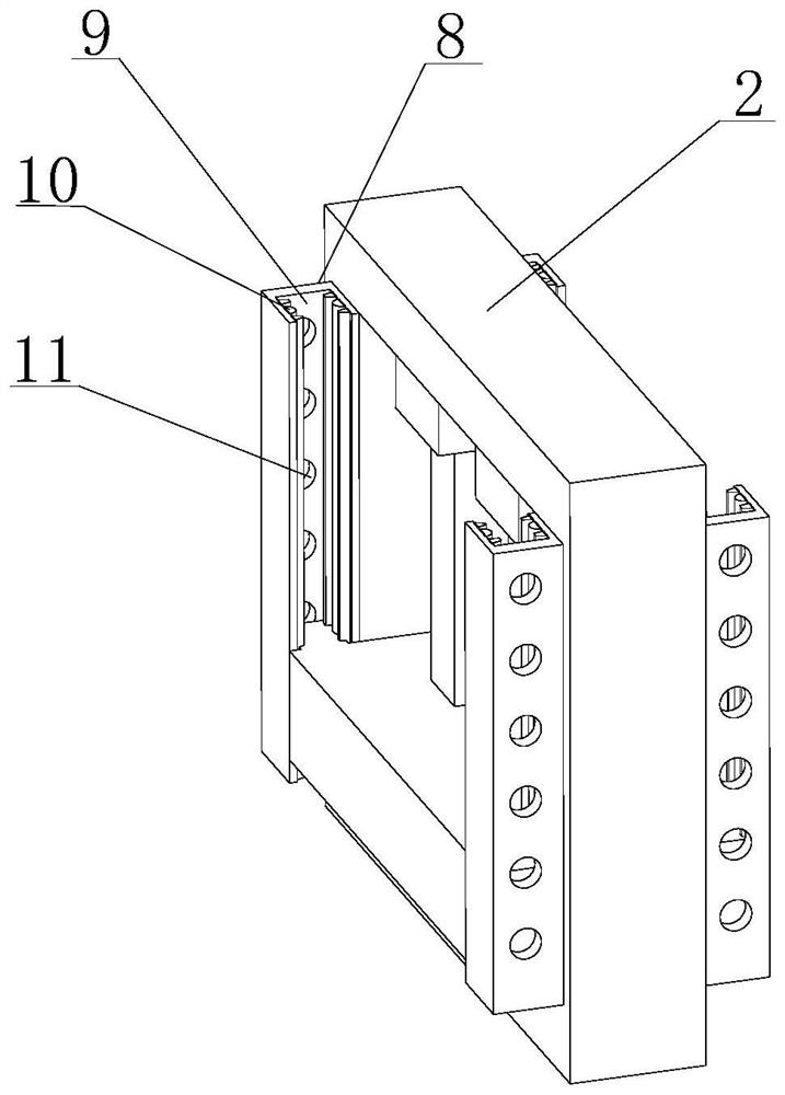
[0041] like Figure 1-6 As shown, on the basis of Embodiment 1, the present invention provides a technical solution: preferably, a card slot block 8 is fixedly connected to the left end of the elevator bracket 2, and a card slot 9 is opened inside the card slot block 8, and the card slot The inner side of 9 is fixedly connected to the limit card block 10, the lower end of the card slot block 8 is provided with a through positioning hole 11, and the end of the support slide 7 close to the card slot block 8 is adapted to the inner side of the set card slot 9, and the card slot block 8 The setting of the card slot 9, the limit block 10 and the through positioning hole 11 can limit the position of the support slide 7 during the movement of the support slide 7, so as to avoid the phenomenon of deviation during the movement. Cause damage to the device, thereby seriously affecting the service life of the device, the support slide 7 is slidably connected along the inner side of the se...

Embodiment 3

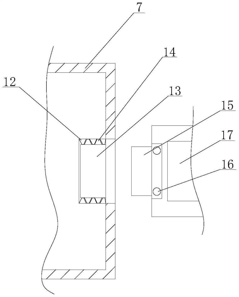
[0043] like Figure 1-6 As shown, on the basis of Embodiments 1 and 2, the present invention provides a technical solution: preferably, the left end of the support plate 6 is fixedly connected with a mounting block 15, and the upper end of the mounting block 15 is movably installed with a limit bolt 16, and the support plate 6 is provided with a groove 17 inside, the right end of the support slide 7 is provided with a mounting groove, and the interior of the mounting groove is provided with an extrusion block 13, the upper end of the extrusion block 13 is fixedly connected with a second trapezoidal friction block 14, The inner side is fixedly connected with a first trapezoidal friction block 12 .

[0044] The arrangement of the first trapezoidal friction block 12 , the extrusion block 13 , the second trapezoidal friction block 14 , the mounting block 15 and the limit bolt 16 allows the support plate 6 and the support slide plate 7 to be installed and clamped together, so that ...


PUM


Abstract

The invention discloses an elevator guide rail structure, and relates to the technical field of elevators, the elevator guide rail structure comprises a guide rail base, the upper end of the guide rail base is fixedly connected with an elevator support, the lower end of the elevator support is fixedly connected with a hydraulic cylinder, the lower end of the hydraulic cylinder is provided with a telescopic rod, and the lower end of the telescopic rod is fixedly connected with a supporting sliding plate; a telescopic assembly is arranged at the upper end of the guide rail base, and a supporting plate is arranged at the upper end of the telescopic assembly. Through arrangement of the elevator support, the hydraulic cylinder, the telescopic rod and the supporting sliding plate, the supporting plate is conveniently pulled, so that an elevator moves, operation of workers is facilitated, according to arrangement of a clamping groove block, a clamping groove, a limiting clamping block and a through positioning hole, the supporting sliding plate can be limited in the moving process, and the working efficiency is improved. And the situation that the service life of the device is seriously affected due to the fact that the device is damaged due to the deviation phenomenon in the moving process is avoided.

Description

technical field [0001] The invention relates to the technical field of elevators, in particular to an elevator guide rail structure. Background technique [0002] Elevator guide rails are elevator components composed of steel rails and connecting plates, which are divided into car guide rails and counterweight guide rails. From the cross-sectional shape, it is divided into three forms: T-shaped, L-shaped and hollow. While the guide rail plays a guiding role, it bears the impact force of the car and elevator during braking, and the impact force of the safety gear during emergency braking. The magnitude of these forces is related to the load quality and speed of the elevator, so the guide rail should be selected according to the elevator speed and load quality. [0003] The following problems exist for the prior art: [0004] 1. Some existing elevator guide rail structures have poor shock absorption effect during operation, and the larger impact force is likely to cause dam...

Claims


Application Information

Patent Timeline
IPC IPC(8): B66B7/02F16F15/02F16F15/067
CPCB66B7/024B66B7/028
Inventor 姚良
Owner 浙江有东电梯配件有限公司
Why Eureka
Try Eureka