
Manhole cover performance testing equipment

A technology for testing equipment and manhole covers, which can be used in containers, packaging, underwater structures, etc., to solve problems such as unguaranteed safety, and achieve the effects of improving efficiency, improving quality, and avoiding offsets.

Inactive Publication Date: 2019-08-02
CHUZHOU JINLU CNC MACHINERY
View PDF6 Cites 0 Cited by
  • Summary
  • Abstract
  • Description
  • Claims
  • Application Information

AI Technical Summary

Problems solved by technology

[0002] At present, there are many applications of manhole covers, which are generally used on storage tanks. Manhole covers are also called normal pressure manhole covers and quick opening manholes. Most chemical vehicle manhole covers are flange manhole covers. The cover is installed on the top of the tank body of the chemical truck. It is a passage for people to enter and exit the tank, and an observation port for checking the goods and the natural conditions inside the tank. Especially when manhole covers transport dangerous or volatile objects, extra care is required. Test the sealing and pressure performance of the manhole cover, and check whether the manhole cover is up to standard through different pressure tests. At present, there is no equipment that can quickly detect whether the manhole cover meets the specifications to deal with such problems, resulting in The safety of the manhole cover cannot be guaranteed. In order to solve the above-mentioned problems, we propose a manhole cover performance testing equipment

Method used


Image

  • Manhole cover performance testing equipment
  • Manhole cover performance testing equipment
  • Manhole cover performance testing equipment

Examples


Embodiment Construction

[0020] In order to make the technical means, creative features, goals and effects achieved by the present invention easy to understand, the present invention will be further described below in conjunction with specific embodiments.

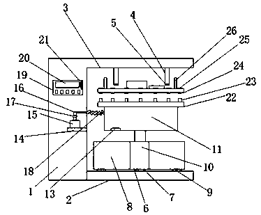
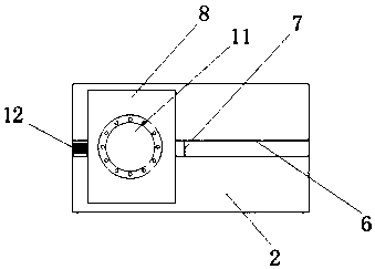
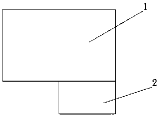
[0021] see Figure 1-3 , the present invention provides a technical solution: a manhole cover performance testing equipment, including a frame 1, the right end of the frame 1 is provided with an L-shaped groove 3, and the bottom end of the side wall of the L-shaped groove 3 is fixed with a support plate 2, The middle part of the support plate 2 top is provided with a block groove 6, and one end of the block groove 6 is equipped with an electro-hydraulic push rod 12. Inside, and the side wall of the slider 7 is connected with the push rod of the electro-hydraulic push rod 12, the top of the slider 7 is fixed with a lifting shell 8, and the bottom of the lifting shell 8 is equipped with a hydraulic cylinder 10, and the piston of the hydraulic cylind...


PUM


Abstract

The invention discloses manhole cover performance testing equipment. The manhole cover performance testing equipment comprises a machine frame, wherein an L-shaped groove is formed in the right end ofthe machine frame, a supporting plate is fixed at the bottom end of the side wall of the L-shaped groove, a block groove is formed in the middle of the top end of the supporting plate, one end of theinterior of the block groove is provided with an electro-hydraulic push rod, a sliding block is fixed on a push rod of the electro-hydraulic push rod, the sliding block is located in the block groove, a side wall of the sliding block is connected with the push rod of the electro-hydraulic push rod, a lifting shell is fixed at the top end of the sliding block, a hydraulic cylinder is arranged at the bottom end inside the lifting shell, a piston rod of the hydraulic cylinder penetrates through the top end of the lifting shell, and the tail end of the piston rod of the hydraulic cylinder is fixed at the bottom end of a detection tank. The detection tank is arranged at the top of the hydraulic cylinder, the manhole cover is placed on a detection disc, so that the hydraulic cylinder is used for driving the manhole cover to be tightly connected with the detection disc, so that the installation time is greatly prolonged, the subsequent detection efficiency is improved, and the manhole coverperformance testing equipment is suitable for being widely popularized and used.

Description

technical field [0001] The invention relates to a testing device, in particular to a performance testing device for a manhole cover. Background technique [0002] At present, there are many applications of manhole covers, which are generally used on storage tanks. Manhole covers are also called normal pressure manhole covers and quick opening manholes. Most chemical vehicle manhole covers are flange manhole covers. The cover is installed on the top of the tank body of the chemical truck. It is a passage for people to enter and exit the tank, and an observation port for checking the goods and the natural conditions inside the tank. Especially when manhole covers transport dangerous or volatile objects, extra care is required. Test the sealing and pressure performance of the manhole cover, and check whether the manhole cover is up to standard through different pressure tests. At present, there is no equipment that can quickly detect whether the manhole cover meets the specific...

Claims


Application Information

Patent Timeline
IPC IPC(8): B65D90/10B65D90/48
CPCB65D90/10B65D90/48
Inventor 李家龙
Owner CHUZHOU JINLU CNC MACHINERY
Learn More