Toilet flusher

A toilet flushing device and toilet flushing technology, which is applied to flushing equipment with water tanks, sanitary equipment for toilets, and indoor sanitary piping installations, etc., which can solve the problems of low concentration and low efficacy of flushing agents

Inactive Publication Date: 2006-08-02
傅子泽
View PDF0 Cites 10 Cited by
  • Summary
  • Abstract
  • Description
  • Claims
  • Application Information

AI Technical Summary

Problems solved by technology

But in the prior art, the toilet flushing agent is put into the bottom of the toilet flushing tank, so that the concentration of the side flushing agent is extremely low, and only a few seconds when flushing the toilet, the side flu

Method used


Image

  • Toilet flusher
  • Toilet flusher
  • Toilet flusher

Examples


Example Embodiment

[0011] Example one:

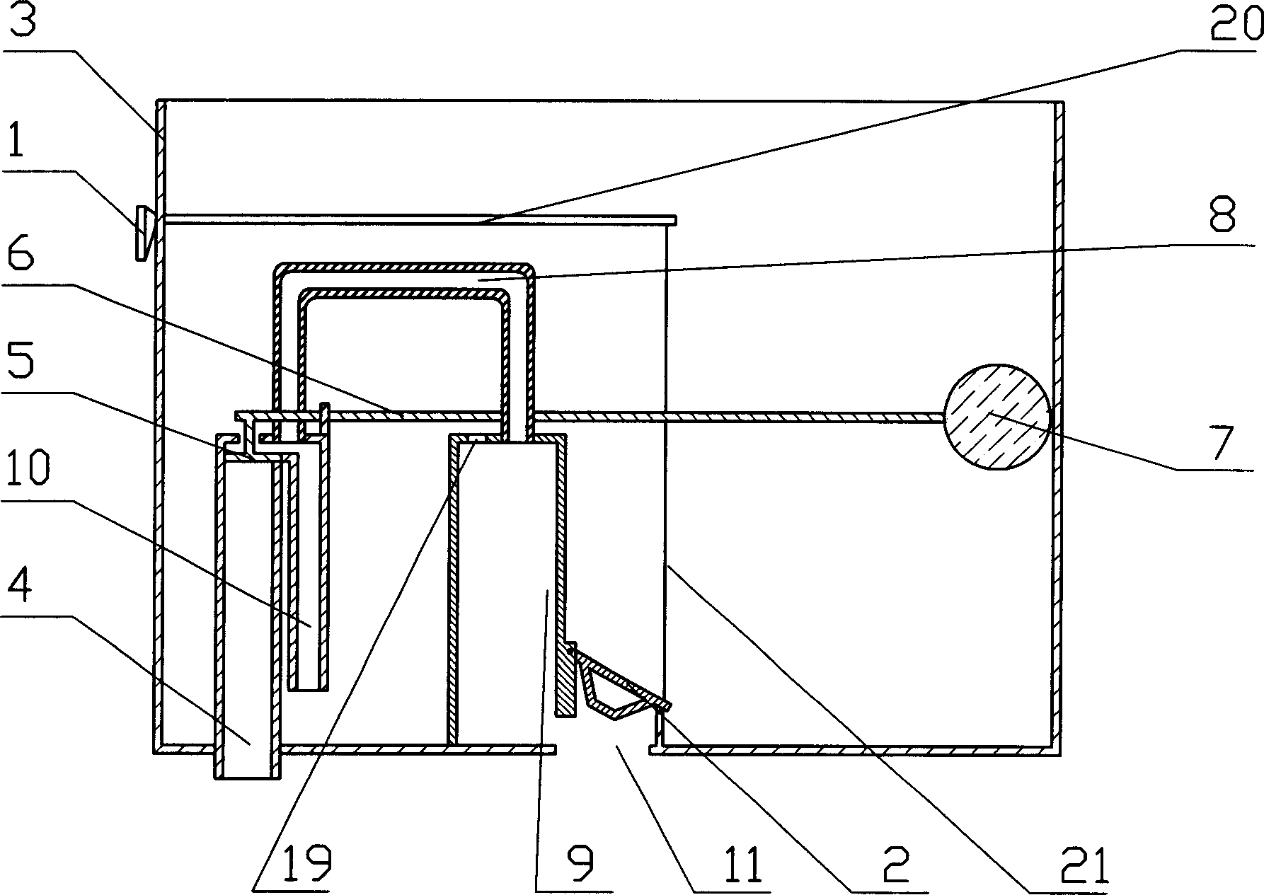
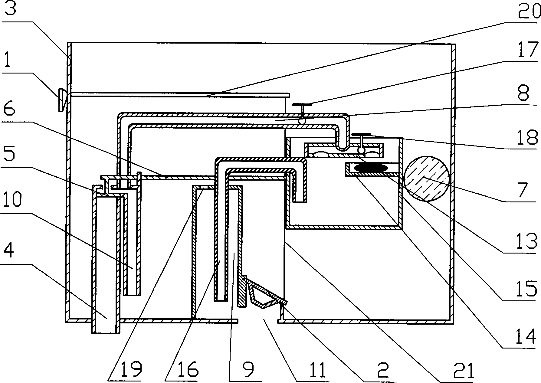
[0012] Such as figure 2 As shown, the present invention includes a water divider 13, a toilet flushing agent box 14, a toilet body 15, and a toilet outlet pipe 16. The present invention is installed in a common flushing water tank. The flushing water tank consists of the handle 1, the drain gate 2, the water tank body 3, the water inlet pipe 4, the water inlet valve 5, the float rod 6, the float ball 7, the secondary flushing water inlet pipe 8, the secondary flushing water pipe 9, the primary The flushing water inlet pipe 10 is composed of the handle 1 is arranged on the upper part of the side wall of the water tank body 3, and the handle 1 is connected to the drain gate 2 through a connecting rod and a rope. The gate 2 is arranged on the upper part of the water outlet 11 at the lower part of the water tank body 3, and the upper part of the water outlet 11 of the drain gate 2 is sealed and matched to ensure that the water tank body stores necessary water. T...

Example Embodiment

[0013] Embodiment two:

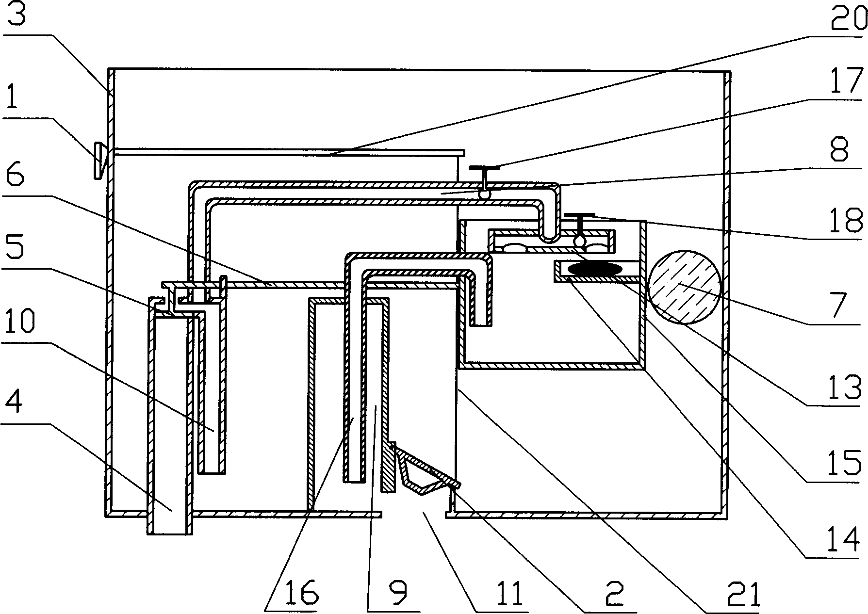
[0014] Such as image 3 As shown, the other structure of this embodiment is the same as that of body embodiment 1, except that the top of the secondary flushing pipe 9 is sealed, and the toilet outlet pipe 16 is also an inverted U-shaped bend, and the The water outlet end of the toilet outlet pipe 16 extends approximately close to the water outlet 11 and is lower than the water inlet end. The bottom of the U-shaped bend pipe is approximately horizontally arranged. After a large amount of one flush, the second There is a certain negative pressure in the flushing pipe 9, and the pressure in the toilet is greater than the pressure in the secondary flushing pipe 9, so the water with the flushing agent dissolved in the toilet can be quickly flushed The underpass to the toilet tray has a better cleaning effect, so the flushing agent can be effectively used, and the cleaning effect is better.


PUM


Abstract

The present invention is one kind of toilet flusher capable of utilizing detergent effectively to reach high cleaning effect. The toilet flusher includes a water dividing head, a detergent box, a flusher body, and a flusher water outlet pipe. The flusher body is fixed inside the cistern, the water dividing head is set inside the flusher body and is connected to the secondary flushing water inlet pipe, the detergent box is set inside the flusher body and below the water inlet of the water dividing head, and the flusher body is connected via the water outlet pipe of the toilet flusher to the secondary flushing water pipe.

Description

technical field [0001] The invention relates to a toilet flusher. Background technique [0002] The flushing water tank is generally composed of a water tank body, a water inlet pipe, a water inlet valve, a floating ball rod, a floating ball, a primary flushing water inlet pipe, a secondary flushing water inlet pipe, a secondary flushing water pipe, a drainage gate, a handle, etc. When flushing the toilet, turn the handle to open the drain gate, and the water in the water tank will be discharged into the toilet pan from the drain port to flush the toilet pan. The water pipe flows in, and most of the water directly enters the water tank through the primary water inlet pipe, while a small part is directly discharged into the toilet pan from the outlet through the secondary water inlet pipe through the secondary flushing pipe (such as figure 1 shown). This kind of flushing water tank, when the drain gate is opened, a large amount of water rushes into ...

Claims


Application Information

Patent Timeline
IPC IPC(8): E03D1/012E03C1/12
CPCE03D9/033
Inventor 傅子泽
Owner 傅子泽
Why Eureka
Try Eureka