Heat exchanger

A technology for heat exchangers and heat exchange areas, applied in heat exchange equipment, heat exchanger shells, indirect heat exchangers, etc., can solve problems such as deterioration of heat exchange performance, serious differences in air temperature distribution, and difficult forward installation

Active Publication Date: 2006-08-02
HANON SYST
View PDF1 Cites 0 Cited by
  • Summary
  • Abstract
  • Description
  • Claims
  • Application Information

AI Technical Summary

Problems solved by technology

Therefore, the air passing between all the tubes 10 does not exchange heat uniformly, so that the temperature distribution difference of the discharged air becomes more serious
In addition, there is a problem of icing on the surface of the evaporator, and the air conditioning system becomes unstable in the subcooled part
In addition, in the overheating part, since the exhausted air is not cooled and dehumidified normally, humid air whose temperature has been raised is introduced into the car, thereby causing discomfort to the occupants
[0019] Due to the action of the fluid communication portion 25 for flow-communicating the inlet side heat exchange portion 20a and the outlet side heat exchange portion 20b installed separately at the end of the tank 2, the pressure drop speed of the refrigerant is increased, causing Deterioration of heat exchange performance and impedes miniaturization of thermal evaporators
[0020] Also, the conventional evaporator has another problem in that since both the inlet pipe 4 and the outlet pipe are arranged at one side of the evaporator 1, it is difficult to arrange them forward

Method used


Image

  • Heat exchanger
  • Heat exchanger
  • Heat exchanger

Examples


Embodiment Construction

[0038] Preferred embodiments of the present invention will now be described in detail with reference to the accompanying drawings.

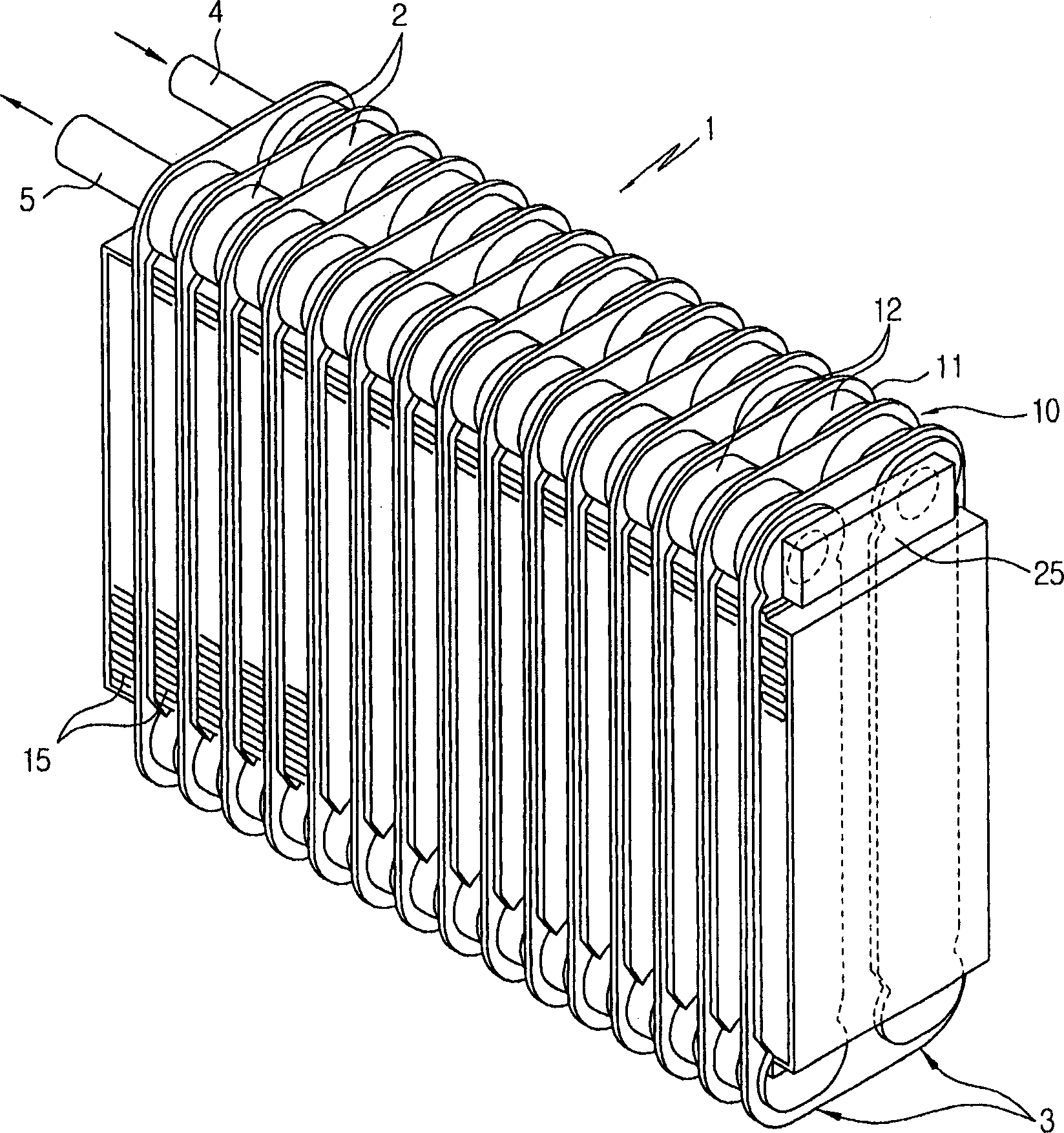
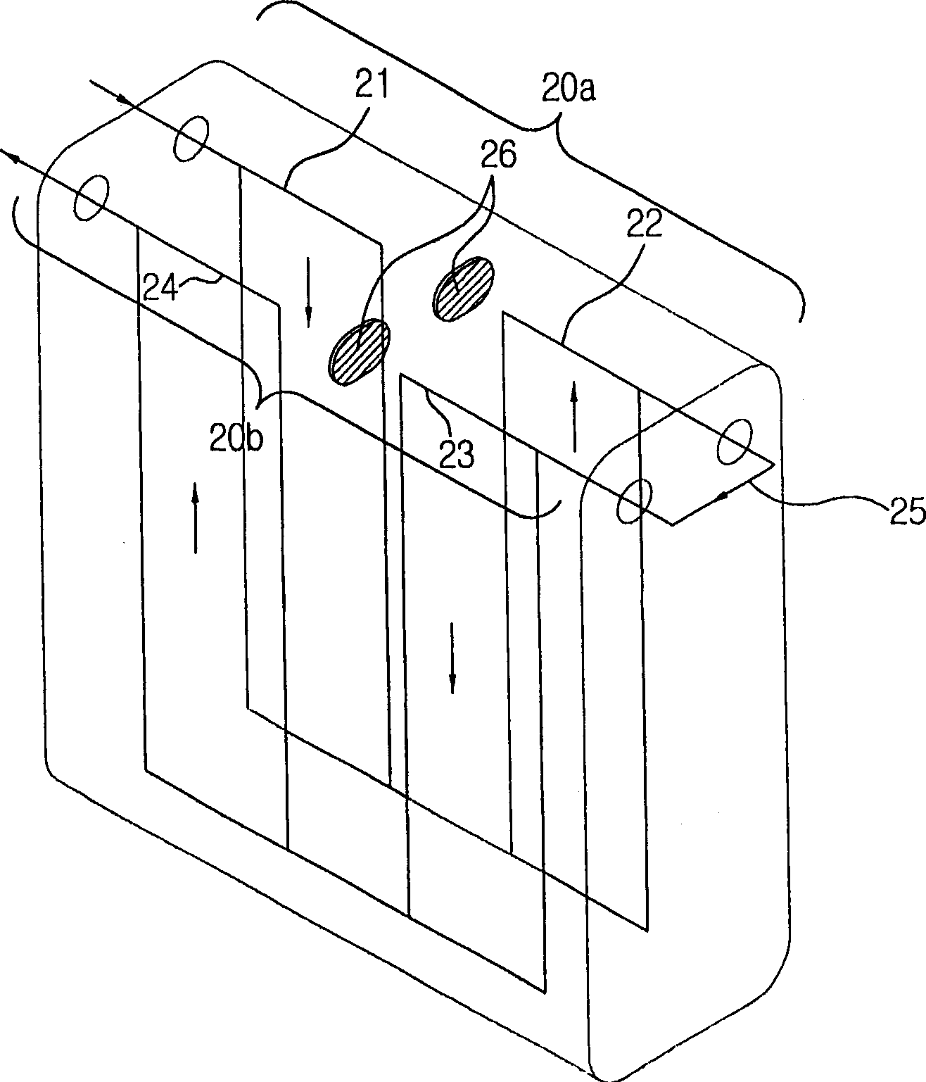
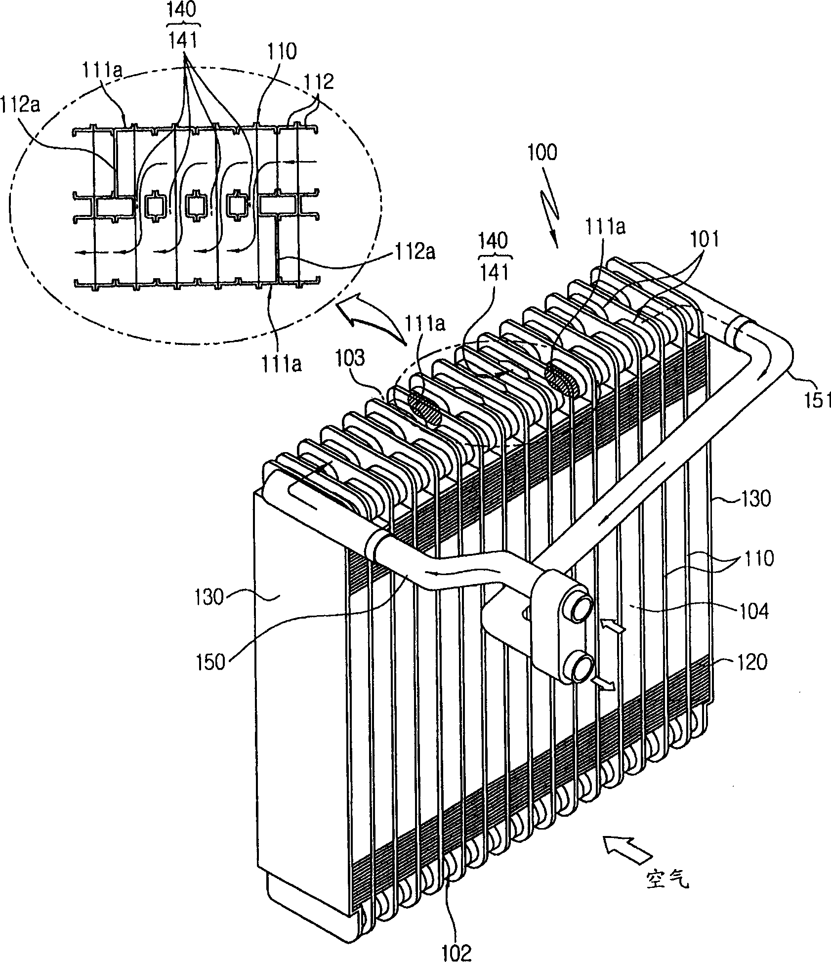
[0039] image 3 is a perspective view of a heat exchanger according to a first preferred embodiment of the present invention, Figure 4 is a front view of the heat exchanger according to the first preferred embodiment, Figure 5 is a perspective view showing a state where the ordinary pipe is separated from the heat exchanger according to this first preferred embodiment, Image 6 is a perspective view showing a state in which a pipe having a fluid communication passage is separated from the heat exchanger according to this first preferred embodiment, Figure 7 is a perspective view showing a state where the separator is separated from the heat exchanger according to the first preferred embodiment, Figure 8 is a graph showing the heat dissipation and the pressure drop rate on the refrigerant side as a function of the ratio of the number of row...


PUM


Abstract

The present invention relates to a heat exchanger, in which inlet and outlet side heat exchange parts are communicated with each other and have the same refrigerant flowing direction by communicating pairs of cups with each other which are located at a predetermined area of the center of the heat exchanger, thereby being easily reduced in size, providing uniform surface temperature distribution and improving heat exchange efficiency by reducing the preponderance and the pressure drop rate of refrigerant and inlet and outlet pipes being easily arranged forward.

Description

technical field [0001] The present invention relates to a heat exchanger, and more particularly to a heat exchanger in which an inlet side and an outlet side heat exchanging portion are in flow communication with each other, The cups are in flow communication with each other and have the same refrigerant flow direction, so that the size can be easily reduced and the surface temperature distribution of the heat exchanger can be uniformed by reducing the preponderance and pressure drop velocity of the refrigerant And the heat exchange efficiency is improved, and the inlet pipe and the outlet pipe can be arranged forward easily. Background technique [0002] Generally, a heat exchanger includes flow channels for allowing a heat exchange medium to flow therein so that the heat exchange medium exchanges heat with external air. Heat exchangers are used in various air conditioning devices and are applied in various forms according to different usage conditions, such as evaporators...

Claims


Application Information

Patent Timeline
Patent Type & Authority Applications(China)
IPC IPC(8): F28D1/02F25B39/02
CPCF28F3/044F28F9/0207F28F9/026F28F13/06
Inventor 吴光宪林弘永
Owner HANON SYST
Why Eureka
Try Eureka