Untwisting pay-off device

A pay-off device and untwisting technology, which is applied in the manufacture of electrical components, circuits, cables/conductors, etc., can solve problems affecting quality, unstable core wire tension, and easy torsion of shielded wires, etc., to achieve quality improvement, stability and reliability tension control effect

Inactive Publication Date: 2011-12-21
黄建为
View PDF1 Cites 0 Cited by
  • Summary
  • Abstract
  • Description
  • Claims
  • Application Information

AI Technical Summary

Problems solved by technology

During the production process, the shielded wire is easily twisted when it is unwound, which affects the quality
The patent document with the publication number CN1088244C discloses an ultra-high-speed core wire winding machine. The winding machine is divided into a pay-off device and a take-up device. The machine hardly vibrates, but its pay-off device also has a little defect
figure 1 Shown is the schematic diagram of the pay-off device of the winding machine, which includes a frame 01 and a pay-off wheel 02 suspended on the frame 01. The defect of this structure is that the pay-off wheel 02 rotates and pays off the wire. In the middle, the center of gravity of the pay-off wheel 02 will move left and right accordingly, and the rotation center and center of gravity of the pay-off wheel 02 are not on the same vertical line, so that the speed of the pay-off wheel 02 is unstable, and the instability of the pay-off wheel 02 makes the core When the thread is in various positions, the tension is not stable, and it is even easy to break the core thread

Method used


Image

  • Untwisting pay-off device
  • Untwisting pay-off device
  • Untwisting pay-off device

Examples


Embodiment Construction

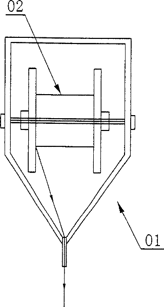
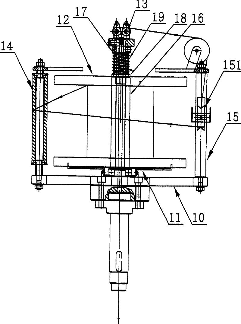
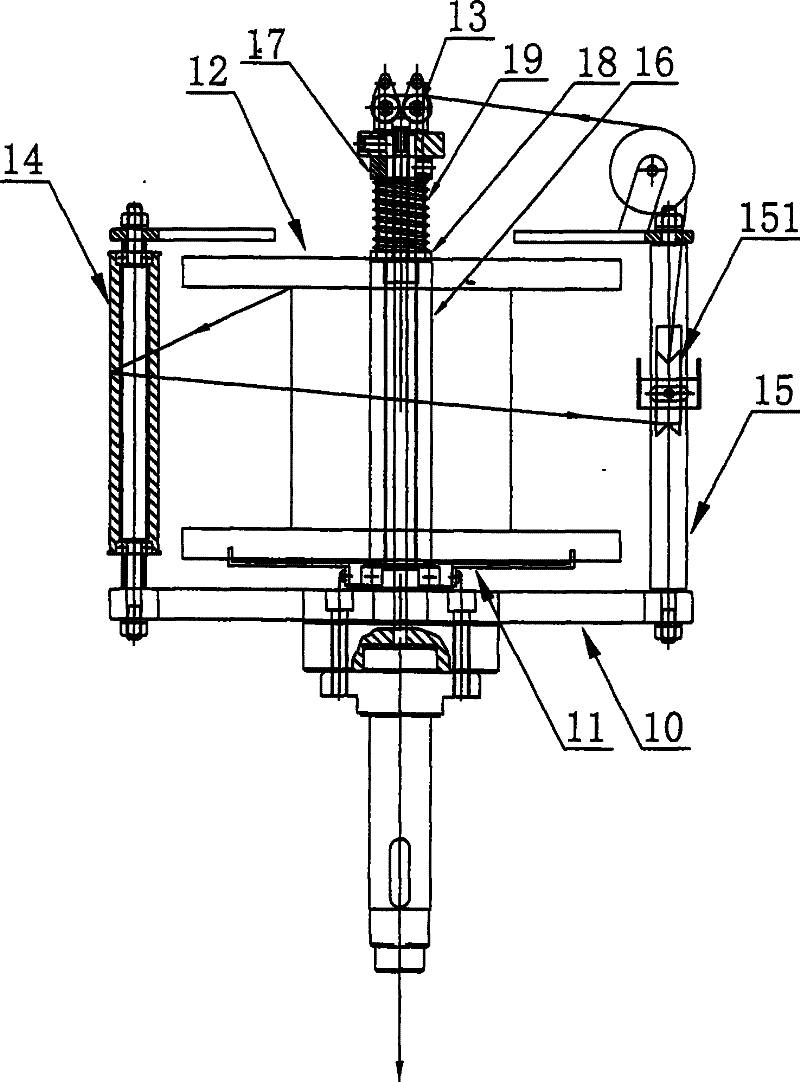
[0013] See attached figure 2 , the present invention includes a frame 10, on which a dial 11 for fixing a pay-off wheel 12 is installed, and the dial 11 is installed in the middle of the frame 10, connected to a motor through a transmission mechanism, and controlled by the motor The disc 11 rotates, so that the pay-off wheel 12 rotates together. When the take-up wheel rotates and pulls the core wire, the pay-off wheel 12 can continue to pay off.

[0014] A hollow shaft 16 is installed coaxially with the dial 11 on the frame of the present invention, the hollow shaft 16 is hollow, and the top is movably fixed with two parallel wire passing wheels 13, and the gap between the two parallel wire passing wheels 13 can be Adjusts to accommodate the passage of core wires of different thicknesses.

[0015] A column 15 is also fixed on the frame 10, and a cable pulley 151 is movably fixed on the column 15. The core wire is sent to the cable pulley 151 after passing around the core wir...


PUM


Abstract

The invention relates to a twist-back pay-off device, which includes a frame, a dial for fixing the pay-off wheel is installed on the frame, the dial drives the pay-off wheel to rotate and pay off, and a plurality of wire passing wheels are fixed on the frame, and the pay-off The core wire on the wheel bypasses the thread-passing wheel for output, and a hollow shaft is installed coaxially with the dial on the frame, the hollow shaft is hollow, and two parallel thread-passing wheels are movable and fixed on the top. The dial is installed in the middle of the frame, and the dial is connected to the motor through a transmission mechanism. A core wire surrounding column is fixed on the frame, and the core wire on the pay-off wheel first bypasses the core wire surrounding column and then other wire passing wheels for output. A column is fixed on the frame, and a cable pulley is movably fixed on the column. An adjusting nut is also arranged on the hollow shaft. The invention can greatly improve the quality of electronic wire products and is suitable for popularization and application.

Description

Technical field: [0001] The invention relates to the technical field of electronic wire production equipment, in particular to an untwisting and untwisting pay-off device used on a winding machine and a stranding machine. Background technique: [0002] With the development of science and technology, shielded wires that can protect the electrical signals flowing through the inner core copper wires from the interference of external electromagnetic fields have been widely used in the national economy and people's livelihood. During the production process, the shielded wire is easily twisted when it is unwound, which affects the quality. The patent document with the publication number CN1088244C discloses an ultra-high-speed core wire winding machine. The winding machine is divided into a pay-off device and a take-up device. The machine hardly vibrates, but its pay-off device also has a little flaw. figure 1 Shown is the schematic diagram of the pay-off device of the winding m...

Claims


Application Information

Patent Timeline
Patent Type & Authority Patents(China)
IPC IPC(8): H01B13/00H01B13/02H01B13/26B65H75/34
Inventor 黄建为
Owner 黄建为
Why Eureka
Try Eureka