Check patentability & draft patents in minutes with Patsnap Eureka AI!

Electronic ballast and power factor callibration circuit

A power factor correction, electronic ballast technology, applied in the direction of electric light sources, electrical components, lighting devices, etc., can solve the problems of unstable voltage and low power factor, and achieve the effects of stable voltage, low manufacturing cost, and reduced consumption

Inactive Publication Date: 2006-08-09
XIAMEN TOPSTAR LIGHTING
View PDF0 Cites 0 Cited by
  • Summary
  • Abstract
  • Description
  • Claims
  • Application Information

AI Technical Summary

Problems solved by technology

The electronic ballast has the following disadvantages: the sampling control switching tube is turned on and off in the oscillation drive circuit, and the power factor is not high; the output voltage of the discharge circuit is unstable

Method used


Image

  • Electronic ballast and power factor callibration circuit
  • Electronic ballast and power factor callibration circuit
  • Electronic ballast and power factor callibration circuit

Examples


Embodiment Construction

[0031] The present invention will be further described below in conjunction with the accompanying drawings.

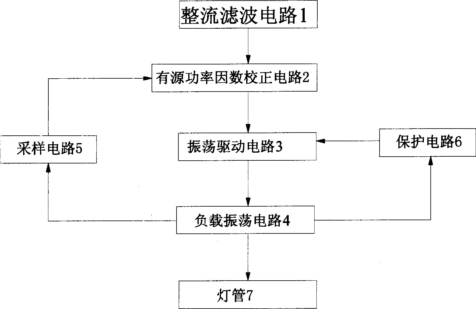
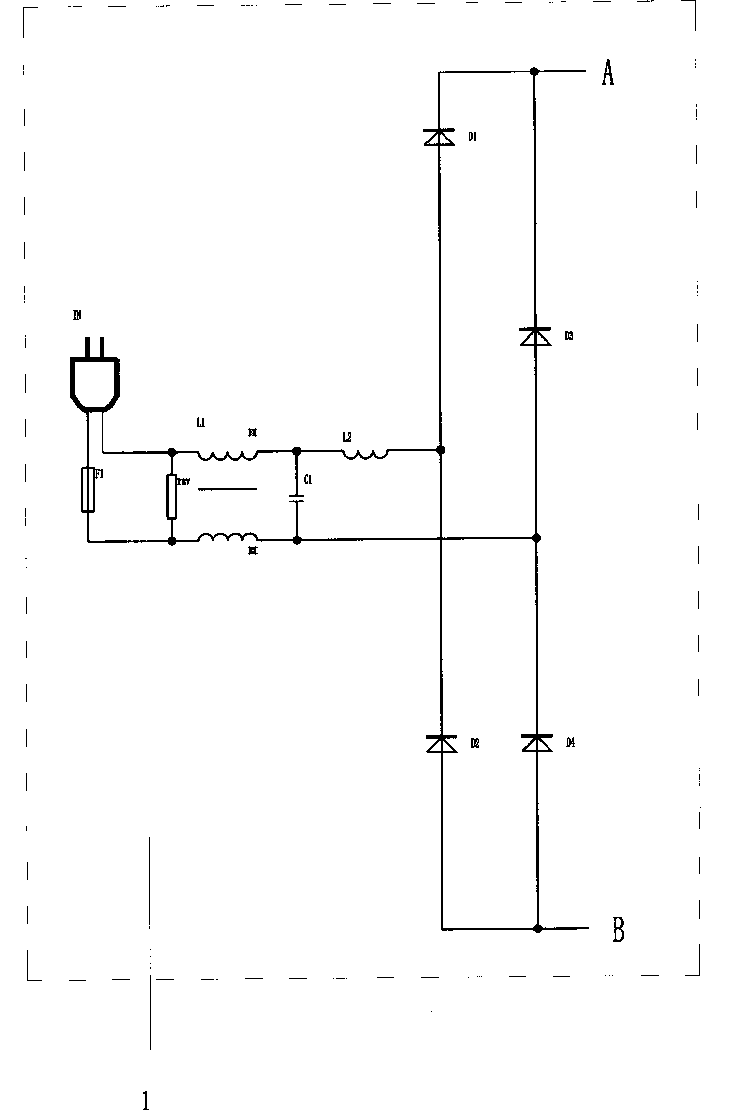
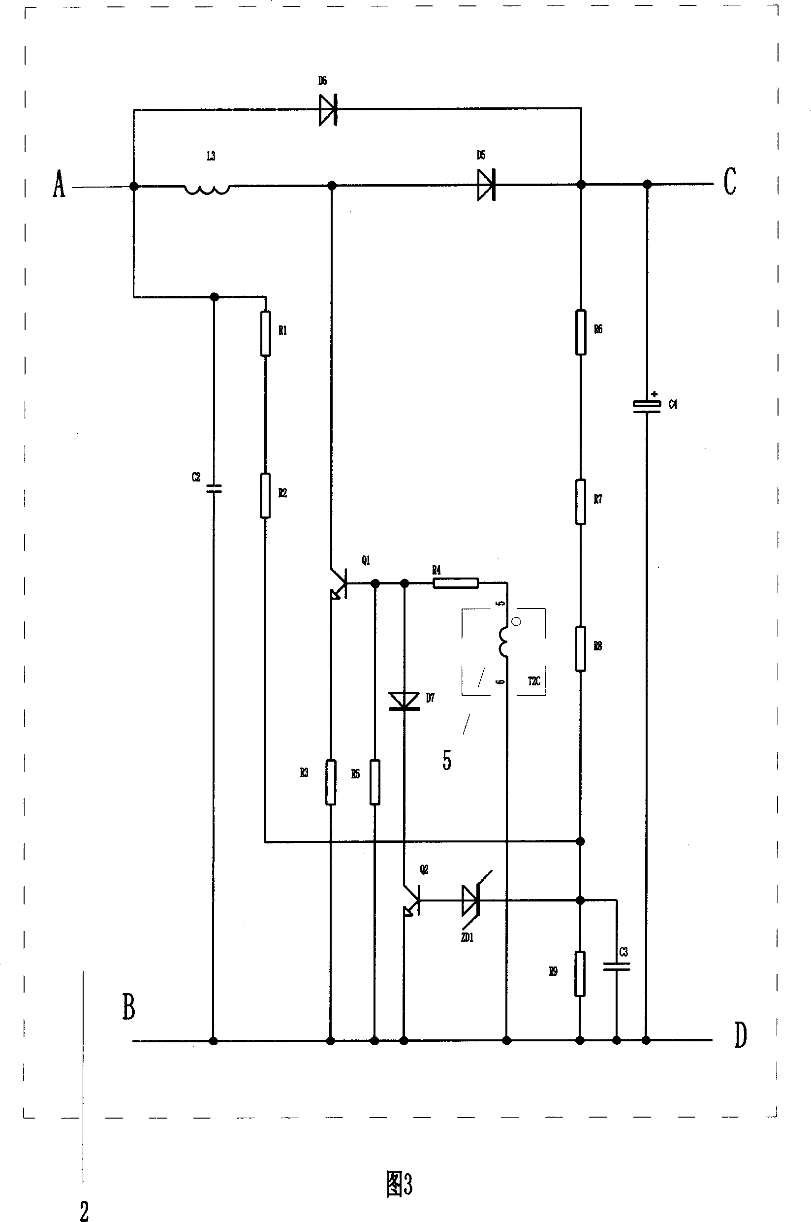
[0032] An electronic ballast in this embodiment, such as figure 1 As shown, it includes a rectification and filtering circuit 1 , an active power factor correction circuit 2 , an oscillation drive circuit 3 , a load oscillation circuit 4 , a sampling circuit 5 and a protection circuit 6 . The rectification filter circuit 1 is connected to an external power supply; the input terminal of the active power factor correction circuit 2 is electrically connected to the output terminal of the rectification filter circuit 1; the input terminal of the oscillation drive circuit 3 is electrically connected to the output terminal of the active power factor correction circuit 2; the input terminal of the load oscillation circuit 4 Electrically connected to the output end of the oscillation driving circuit 3; the lamp tube 7 is connected to the output end of the load oscillation circ...


PUM


Abstract

The correction circuit for power factor is composed of discrete parts. Using electrical signal sampled from circuit of load oscillation, the invention controls first switch tube of the correction circuit to keep follow current in all band supplied by rectifying and filtering circuit in order to raise power factor. The disclosed correction circuit is adopted by correction circuit for power factor of the disclosed electronic ballast. Advantages are: follow current in all band, power factor larger than 0.97, and power factor at input side raised to more than 0.99, total harmonic distortion reduced lower than 10úÑ, stable voltage output from discharge circuit, and low fabricating cost. Moreover, the invention reduces harmonic wave fed back to electric network greatly so as to save energy sources, lower consumption and reduce pollution on electric network.

Description

technical field [0001] The invention relates to an electronic ballast and a power factor correction circuit. Background technique [0002] An existing electronic ballast includes a rectification and filtering circuit, a power factor correction circuit, an oscillation drive circuit, a load oscillation circuit and a protection circuit; the rectification and filtering circuit is connected to an external power supply; the input end of the power factor correction circuit is electrically connected to the output end of the rectification and filtering circuit The input end of the oscillation drive circuit is electrically connected to the output end of the power factor correction circuit; the input end of the load oscillation circuit is electrically connected to the output end of the oscillation drive circuit; the lamp tube is connected to the output end of the load oscillation circuit. The power factor correction circuit includes: a switch circuit, which includes a switch tube, and ...

Claims


Application Information

Patent Timeline
IPC IPC(8): H05B41/295H05B41/298
Inventor 李智国
Owner XIAMEN TOPSTAR LIGHTING
Features
  • R&D
  • Intellectual Property
  • Life Sciences
  • Materials
  • Tech Scout
  • Unparalleled Data Quality
  • Higher Quality Content
  • 60% Fewer Hallucinations
Learn More