Cruciform spring element

A technology of components and cross springs, which is applied in the field of cross-shaped or cross spring components, can solve problems such as changes in spring stiffness or elastic coefficient, and achieve the effect of small hysteresis

Active Publication Date: 2006-08-16
SCHENCK PROCESS EURO GMBH
View PDF2 Cites 17 Cited by
  • Summary
  • Abstract
  • Description
  • Claims
  • Application Information

AI Technical Summary

Problems solved by technology

However, such cross-spring elements have some disadvantages, especially with regard to rotational radial loads, and there is the danger that the spring properties may change abruptly or in steps depending on the stress or tension of the leaf spring, which will lead to Large bending (critical) loads with undesired changes in spring rate or spring rate in the direction of rotation

Method used


Image

  • Cruciform spring element
  • Cruciform spring element

Examples


Embodiment Construction

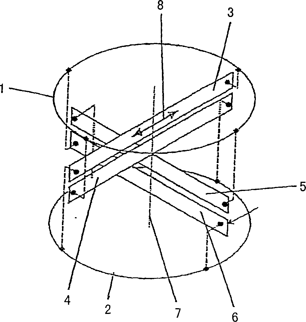
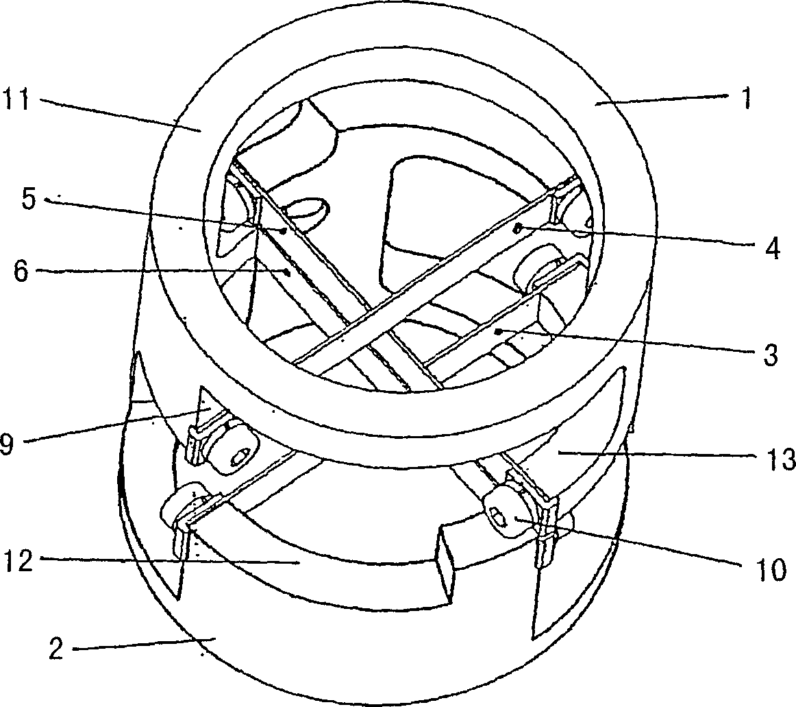
[0016] exist figure 1 In , a cross-spring element for a mass flow measurement device according to the Coriolis principle is schematically shown. The cross spring element consists of 4 pairs of cross leaf springs 3 , 4 , 5 , 6 which are fastened to two annular bearing elements 1 , 2 .

[0017] This cross-spring element is provided in particular to connect the drive shaft of the impeller, which is mounted in a bushing not shown, to the pivotally or pendulously mounted force-measuring device. Such a device is disclosed in patent application number 10253078.5-52 filed with the German Patent and Trademark Office on November 13, 2002. In this respect, the force-measuring device is supported by an intermediate transmission on the drive motor. To this end, the bearing elements 1 , 2 are each connected to a toothed gear which rotates in mesh with two intermediate gears of similar type and which are synchronously driven by a drive motor. In this respect, one of the intermediate gears...


PUM


Abstract

The invention relates to a cruciform spring element as preferably mounted in measuring devices for measuring the mass flow rate of bulk materials according to the Coriolis principle. To this end, two bearing elements (1, 2) that can turn relative to one another are provided in the measuring branch and have at least four leaf spring elements (3, 4, 5, 6) that cross one another in an orthogonal manner and join both bearing elements (1, 2) to one another. The crossing leaf spring elements (3, 4; 5, 6) of one radial direction (8) are arranged at least in pairs and cross at the rotational axis (7). The ends of each leaf spring pair (3, 4; 5, 6) are respectively fastened, on one side, to different bearing elements (1, 2) whereby transferring radial pressure loads and tensile loads in each direction (8) at the same time.

Description

technical field [0001] The invention relates to a cross-shaped or cross spring element as described in the preceding part of claim 1 of the present application. Background technique [0002] In order to measure rotational moments or torques precisely, it is often necessary to support two parts which are rotatable relative to each other. Especially when small torques are involved, it is critical for the accuracy of the measurement to provide the greatest possible friction-free bearing support. According to the Coriolis measuring principle, relatively low torques are used in particular for measuring mass flow. In such a measuring device, a motor is driven at a constant rotational speed, which rotates an impeller on which the material flow is deposited and radially deflected. The drive torque is measured by a torque measuring device and its magnitude is proportional to the mass flow. [0003] A measuring device for determining the continuous weight of a material flow is prev...

Claims


Application Information

Patent Timeline
Patent Type & Authority Applications(China)
IPC IPC(8): G01F1/80F16C11/12F16D3/00G06K7/10
CPCG01F1/80G01F1/8409G01F1/8454F16C11/12
Inventor 延斯·卡勒罗伯特·魏南德
Owner SCHENCK PROCESS EURO GMBH
Why Eureka
Try Eureka