Electrophoretic display unit

An electrophoretic display and electrophoresis technology, which is applied to static indicators, instruments, etc., can solve the problems of inflexible driving of electrophoretic display units.

Inactive Publication Date: 2006-08-16
KONINKLIJKE PHILIPS ELECTRONICS NV
View PDF1 Cites 4 Cited by
  • Summary
  • Abstract
  • Description
  • Claims
  • Application Information

AI Technical Summary

Problems solved by technology

[0010] Known electrophoretic display units have disadvantages, in p...

Method used


Image

  • Electrophoretic display unit
  • Electrophoretic display unit
  • Electrophoretic display unit

Examples


Embodiment Construction

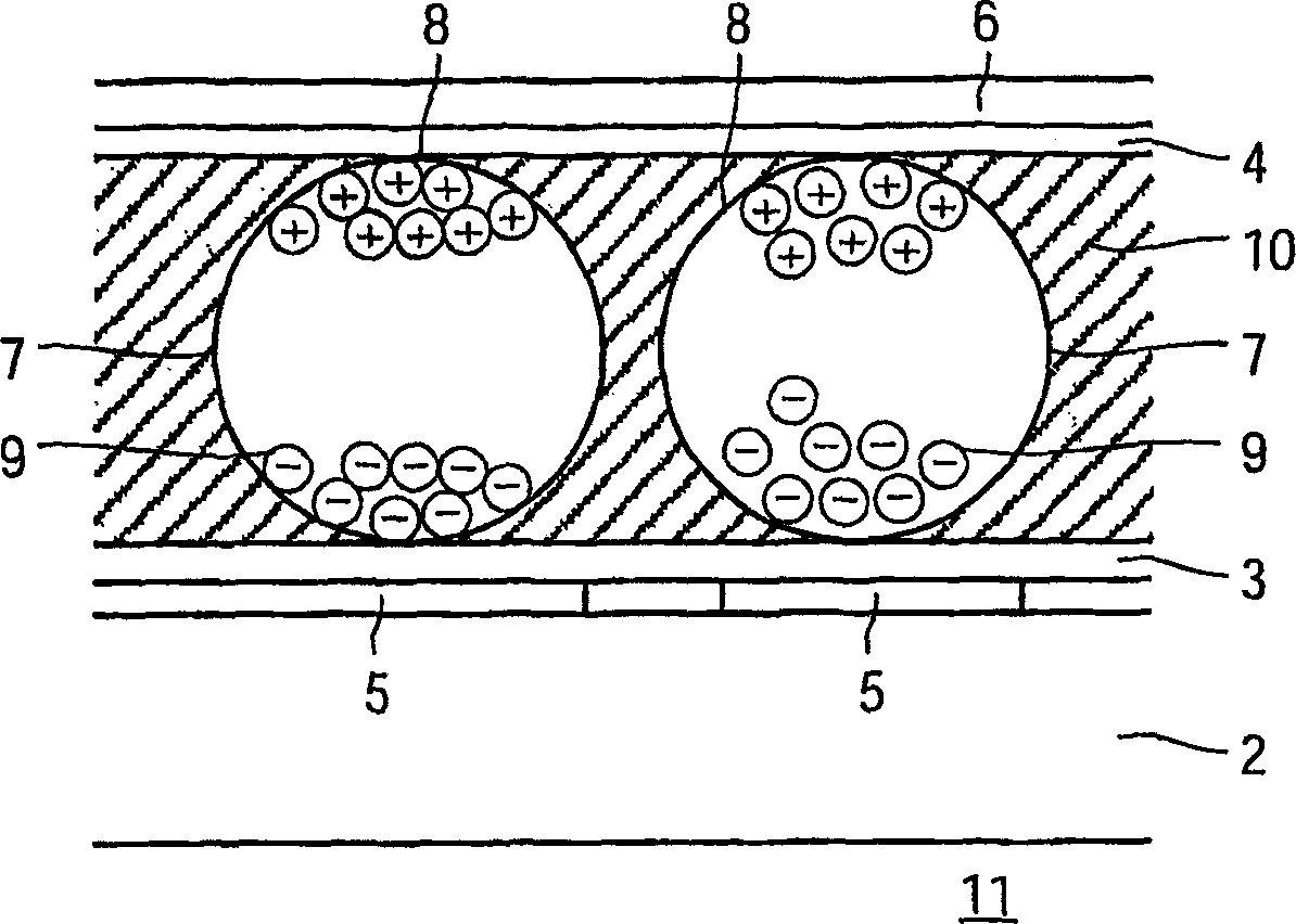
[0034] figure 1 The pixel 11 of the electrophoretic display unit shown (in cross section) comprises a base substrate 2, an electrophoretic film (laminated on the base substrate 2) with electronic ink present on two transparent substrates such as polyethylene Between the substrates 3 and 4 , one substrate 3 is provided with a transparent pixel electrode 5 , and the other substrate 4 is provided with a transparent common electrode 6 . Electronic ink comprises a plurality of microcapsules 7 approximately 10 to 50 microns in diameter. Each microcapsule 7 comprises positively charged white particles 8 and negatively charged black particles 9 suspended in a liquid 10 . When a positive electric field is applied to the pixel electrode 5, the white particles 8 move to the side of the microcapsule 7 pointing to the common electrode 6, and the pixel can be seen by the viewer. At the same time, the black particles 9 move to the opposite side of the microcapsules 7, where they are hidden...


PUM


Abstract

Electrophoretic display units (1) having fixed frame times are driven relatively unflexibly. By introducing line driving signals having timing parameters, the frame rates can be made variable. With variable frame rates, the optical disturbance from shaking pulses (Sh) is reduced and the number of gray values is increased. The timing parameters comprise delays of starts of line driving signals and/or comprise durations of line driving signals. The lines preferably comprise rows. All possible column driving signals and, per column driving signal or per frame, a row delay parameter defining a row delay time, are stored in a memory coupled to the controller (20). Shaking pulses (Sh) are supplied at minimum row delay time, reset pulses (R) are supplied at maximum row delay time, and driving pulses (Dr) are supplied at flexible row delay time, which corresponds with a product of a predefined timeinterval and a step value defined by a number of bits.

Description

technical field [0001] The invention relates to an electrophoretic display unit, a display device comprising an electrophoretic display unit, a method of driving an electrophoretic display unit and a processor program product for driving an electrophoretic display unit. [0002] Examples of display devices of this type are: monitors, laptop computers, personal digital assistants (PDAs), mobile phones and electronic books, electronic newspapers and electronic magazines. Background technique [0003] A prior art electrophoretic display unit is known from International Patent Application WO 99 / 53373. This patent application discloses an electronic ink display comprising two substrates, one substrate is transparent and has a common electrode (also called a counter electrode), and the other substrate is provided with pixel electrodes arranged in rows and columns. One intersection between row and column electrodes is associated with one pixel. A pixel is formed between a part of...

Claims


Application Information

Patent Timeline
IPC IPC(8): G09G3/34G09G3/20
CPCG09G3/2025G09G2310/061G09G3/2014G09G2310/06G09G2300/08G09G2310/068G09G2300/0876G09G3/344
Inventor G·周N·阿里内M·亚苏伊M·T·约翰逊
Owner KONINKLIJKE PHILIPS ELECTRONICS NV
Why Eureka
Try Eureka