
Driving apparatus and driving method of light emitting display panel

A driving device and light-emitting driving technology, applied in lighting devices, electroluminescent light sources, light sources, etc., can solve the problem of a significant degree of shadow occurrence

Inactive Publication Date: 2006-08-23
TOHOKU PIONEER CORP
View PDF1 Cites 4 Cited by
  • Summary
  • Abstract
  • Description
  • Claims
  • Application Information

AI Technical Summary

Problems solved by technology

[0038] On the other hand, it is known that the lower the dimming value is set in the dimming display that controls the overall brightness and darkness of the display screen, the more prominent the occurrence of the above-mentioned shadows is.

Method used


Image

  • Driving apparatus and driving method of light emitting display panel
  • Driving apparatus and driving method of light emitting display panel
  • Driving apparatus and driving method of light emitting display panel

Examples


Embodiment Construction

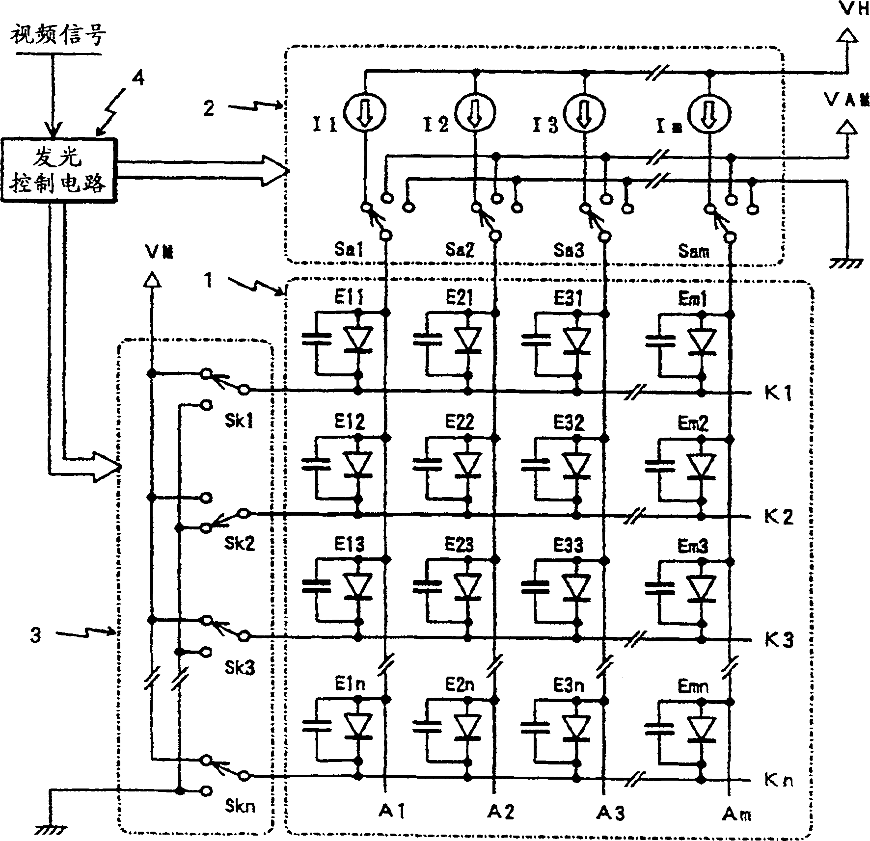
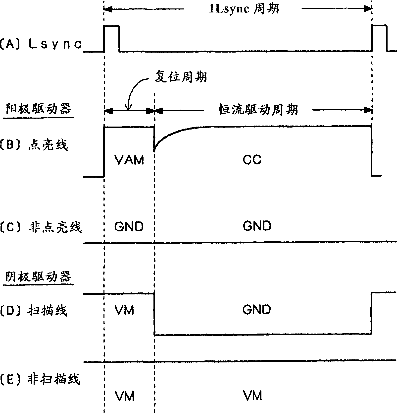
[0051] Hereinafter, the driving device of the light-emitting display screen of the present invention will be described according to the embodiment shown in the figure. As mentioned above, the basic concept of the driving device of the present invention is to variably control the scanning selection potential according to the ratio PN of the light-emitting elements to be scanned and lighted. .

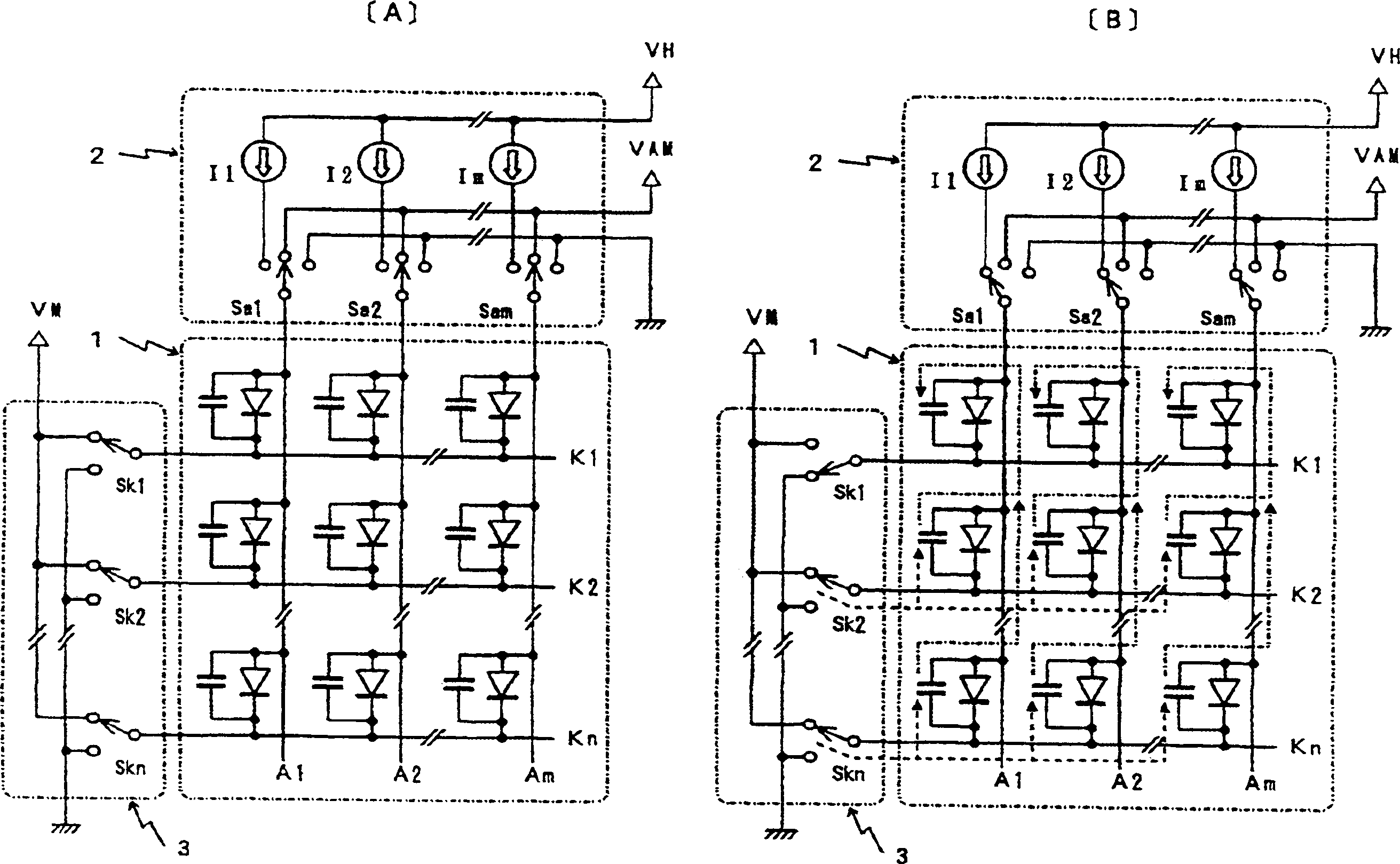
[0052] That is, if Figure 4 (B) As shown by the dotted line, the amount of current flowing from the reverse bias voltage source VM into the unscanned EL element corresponding to the anode line Am (the reflux current) can be appropriately controlled by variably controlling the scanning selection potential. Accordingly, the above-mentioned enhancement in the emission luminance of the EL element to be scanned and turned on can be suppressed, and as a result, the above-mentioned shading can be prevented from occurring.

[0053] The driving device of the present invention basically adopts a...


PUM


Abstract

An analog image signal is supplied to a driving controlling circuit and an A / D converting circuit and is converted to image data corresponding to each one pixel by the A / D converting circuit and is written to an image memory. The image data is read from the image memory for each one scanning and the driving controlling circuit acquires the rate of organic EL devices to be lighted and controlled (lighting rate of light emitting devices for each one scanning). The data of a scanning selecting potential is read from a look-up table based on lighting rate and the data of dimmer setting and a scanning selecting potential in scanning selecting potential setting means is determined by the data of a scanning selecting potential. Current transiently charged to devices to be lighted from a non-scanning selecting power source (reverse bias power source) at the beginning of lighting of the light emitting devices because of a decrease in lighting rate is controlled as appropriate, whereby the occurrence of shadowing can be controlled.

Description

technical field [0001] The present invention relates to a driving device and a driving method suitable for a passive matrix light-emitting display screen using a capacitive light-emitting element. A driving device and a driving method of a light-emitting display that can be reduced to a practically non-problematic level. Background technique [0002] With the popularization of mobile phones and portable information terminals (PDAs), etc., the demand for display screens with high-definition image display functions and low power consumption can be realized. In the past, liquid crystal display screens were used in many products. As a display that meets this requirement. On the other hand, recently, an organic EL (electroluminescence) element that utilizes the characteristics of a self-luminous element has been put into practical use, and it is attracting attention as a next-generation display that replaces a conventional liquid crystal display. The background is that by using...

Claims


Application Information

Patent Timeline
Patent Type & Authority Applications(China)
IPC IPC(8): G09G3/32G09G3/30G09G3/20H05B33/08H05B33/14H05B44/00
CPCG09G3/3216
Inventor 青木俊彥
Owner TOHOKU PIONEER CORP
Learn More