Pipe joint

A technology for pipe joints and joint holes, which is applied in the field of pipe joints and can solve problems such as inability to ensure airtightness and pressure resistance

Inactive Publication Date: 2006-08-23
IHARA SCIENCE CORPORATION +1
View PDF2 Cites 8 Cited by
  • Summary
  • Abstract
  • Description
  • Claims
  • Application Information

AI Technical Summary

Problems solved by technology

[0015] The object of the present invention is to solve the problem that occurs when the nut is removed from the joint main body and the pipe and the sleeve are pulled out from the joint main body to rejoin the pipe by using them, that is, to solve the problem that the airtightness and pressure resistance cannot be ensured.

Method used


Image

  • Pipe joint
  • Pipe joint
  • Pipe joint

Examples


Embodiment Construction

[0043](the whole frame)

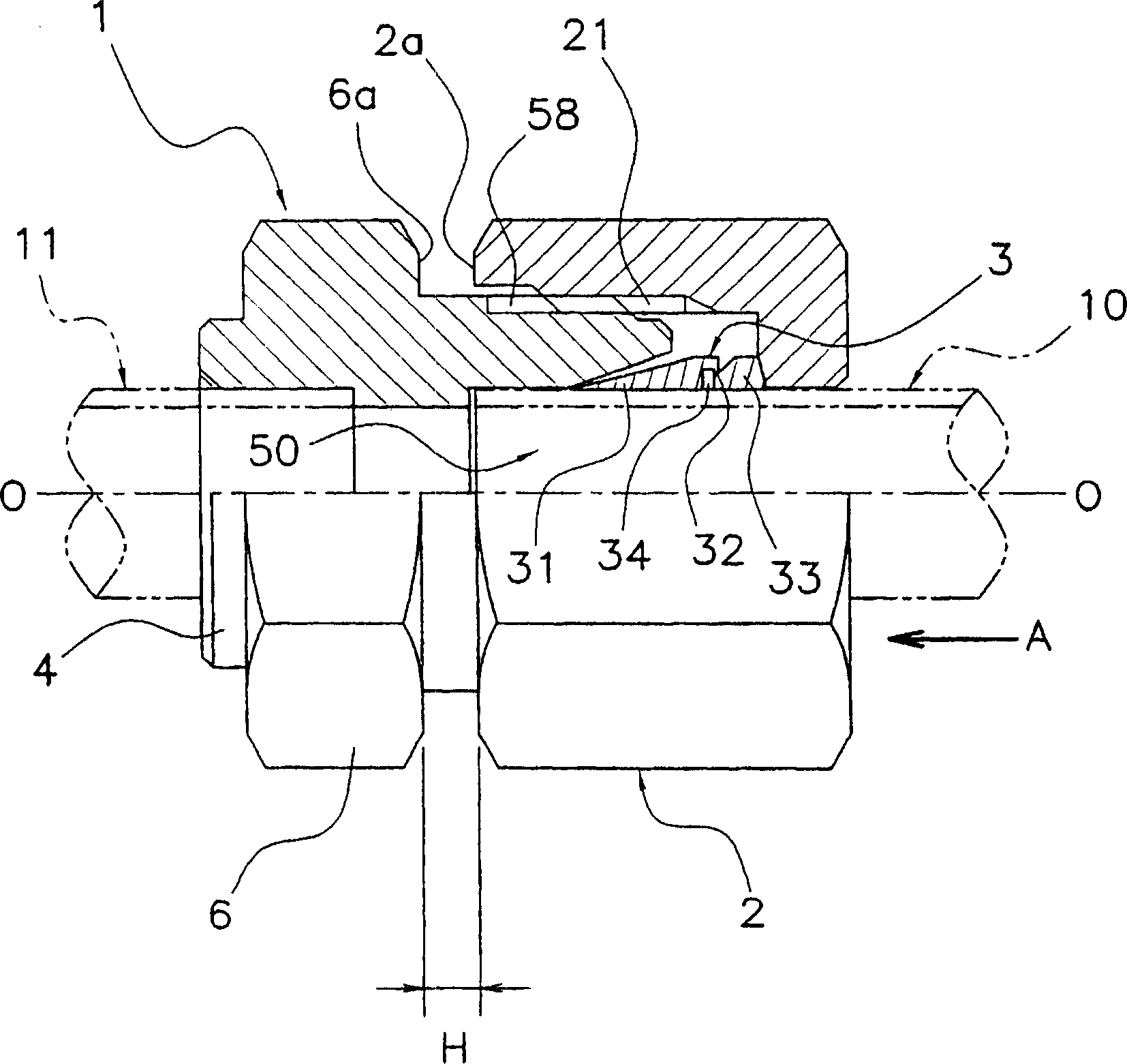
[0044] Such as figure 1 As shown, a pipe joint (cut joint) according to an embodiment of the present invention has a joint main body 1 , a nut 2 and a sleeve 3 . The joint of this embodiment is used to connect a pipe 10 which is a copper pipe or a thin-walled stainless steel pipe and a pipe 11 , and the pipe 10 is detachably engaged in an engaging hole 50 (described later) of the joint main body 1 .

[0045] (Structure of Joint Body 1)

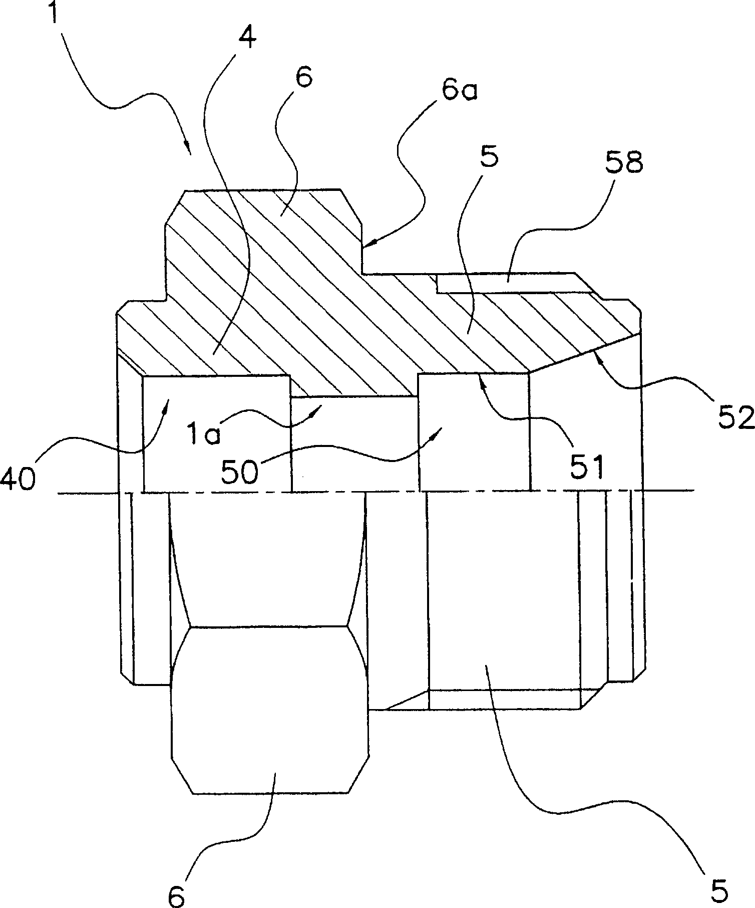
[0046] Such as figure 1 and figure 2 As shown, the joint main body 1 is composed of the following parts: a socket part 4 for inserting and brazing a pipe 11 in an inner hole 40; a pipe connecting part 5 for connecting the pipe 10; a nut part 6 provided on the outer periphery . The side surface 6a of the nut part 6 is an opposing surface which opposes the side surface 2a of the nut 2 mentioned later.

[0047] Such as figure 2 As shown, the inside of the pipe connection portion 5 has an engaging hole forming ...


PUM


Abstract

It is an object of the present invention to resolve problems resulting from removing a nut, pulling a pipe and a sleeve out from a joint main body, and then using these items to rejoin the pipe, that is, to resolve the problems of not being able to ensure airtightness or pressure resistance. The joint according to the present invention comprises a joint main body (1) having a joining hole (50) and an external threaded part (58), as well as a sleeve (3) and a nut (2). The nut (2) is screwed onto the external threaded part (58) in a state in which the pipe (10) and sleeve (3) are inserted through the joining hole (50), and is used to join the pipe (10) to the joining hole (50) via the sleeve (3). The sleeve (3) is tightly fitted to the pipe (10) and the joint main body (1) by the screwing of the nut (2), and is cut off through a linking part (32) that links a sleeve main body (31) and a separating part (33). The sleeve (3) can no longer join the pipe (10) to the joining hole (50) after the nut (2) is removed and the pipe (10) and the sleeve (3) are pulled out from the joining hole (50).

Description

technical field [0001] The present invention relates to a pipe joint, in particular to a pipe joint in which a pipe and a sleeve are inserted into a joint hole of a joint main body, and a nut is screwed onto a threaded portion of the joint main body. Background technique [0002] Joints (pipe joints) used in fluid pipes through which fluid flows are often detachable so that they can be easily replaced or repaired in the event of deterioration of the pipe or fluid supply source. As the pipe joint, there are pipe joints of various thread structures according to the application. [0003] In air conditioners and other equipment, refrigerant flows through fluid pipes, and flare joints are often used as pipe joints. Recently, in consideration of the impact on environmental warming, research has been conducted on replacing Freon with a high-pressure Freon substitute, carbon dioxide, or flammable hydrocarbons as refrigerants. [0004] For example, when hydrocarbon is used as a ref...

Claims


Application Information

Patent Timeline
Patent Type & Authority Applications(China)
IPC IPC(8): F16L19/08F16L19/06
CPCF16L19/10F16L19/103F16L19/00F16L19/06F16L19/08
Inventor 浅川守田中顺一郎藤波功中田春男
Owner IHARA SCIENCE CORPORATION
Why Eureka
Try Eureka