Air conditioner
An air conditioner and main body technology, applied in air conditioning systems, space heating and ventilation, space heating and ventilation details, etc., can solve problems such as turbulent flow, difficult to wipe and clean, easy to adhere to dust, etc.
- Summary
- Abstract
- Description
- Claims
- Application Information
AI Technical Summary
Problems solved by technology
Method used
Image

Examples
Embodiment 1
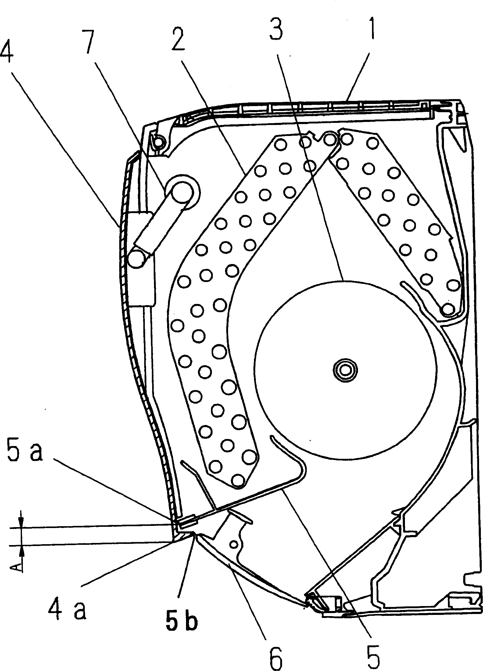
[0025] Next, use figure 1 , 2 A first embodiment of the present invention will be described. In addition, the same symbols and names are used for the parts that are the same as those in the conventional examples, and their descriptions are omitted.
[0026] figure 1 is a cross-sectional view of the indoor unit main body 1 of the air conditioner in this embodiment when the operation is stopped; figure 2 It is a cross-sectional view of its operation.
[0027] figure 1 Among them, in the inside of the main body 1, a heat exchanger 2, a fan 3, and a blowing grill 5 are disposed. On the outlet 5b, blades 6 are provided for changing the direction of the blown air and changing the up and down wind direction.
[0028] On the front of the main body 1, a front fender 4 is provided, and the front fender 4 is connected to the main body 1 by a bracket 7 which is rotationally driven by a driving device not shown. No opening for taking in air is provided in the front panel 4 .
...
Embodiment 2
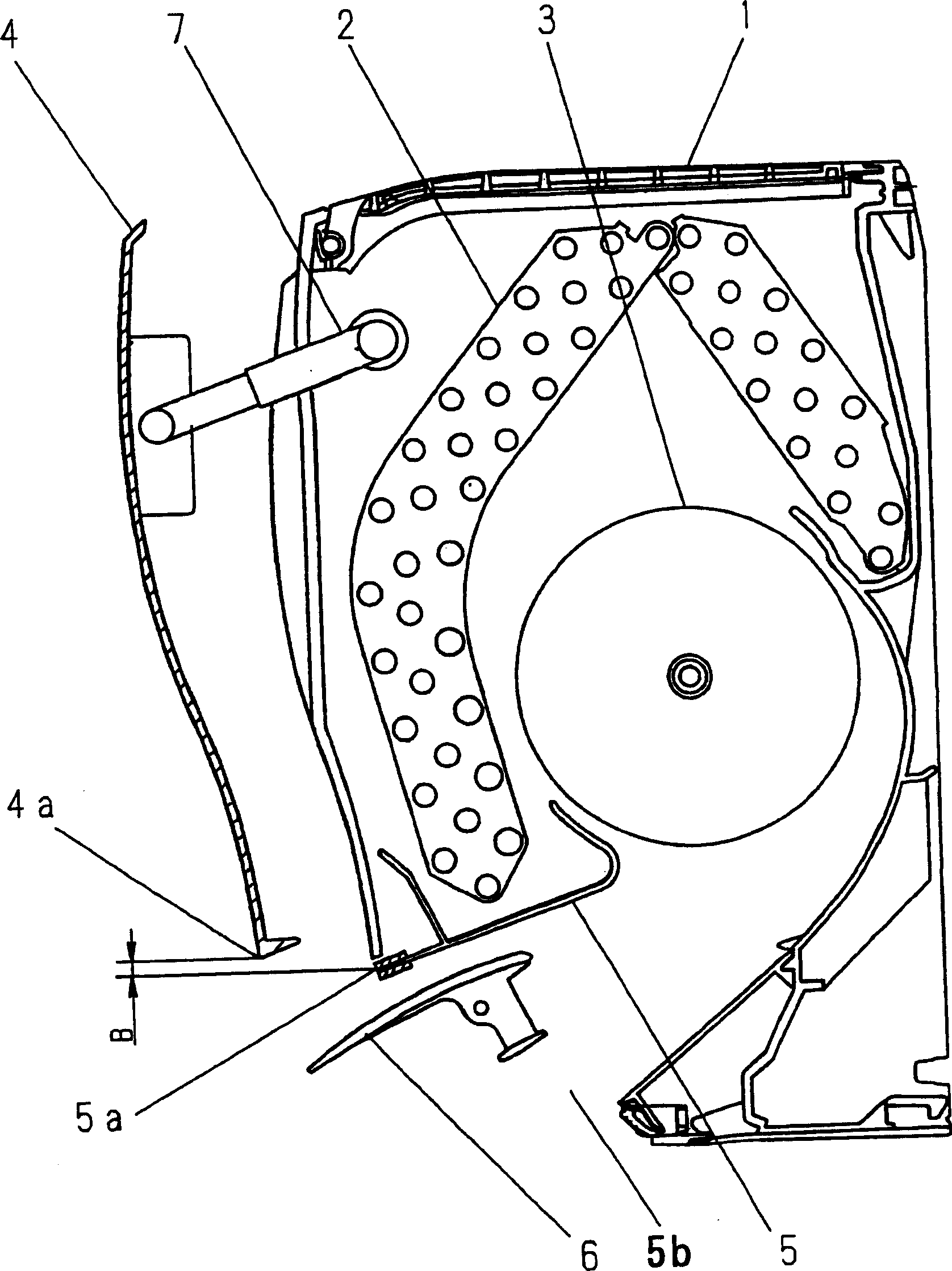
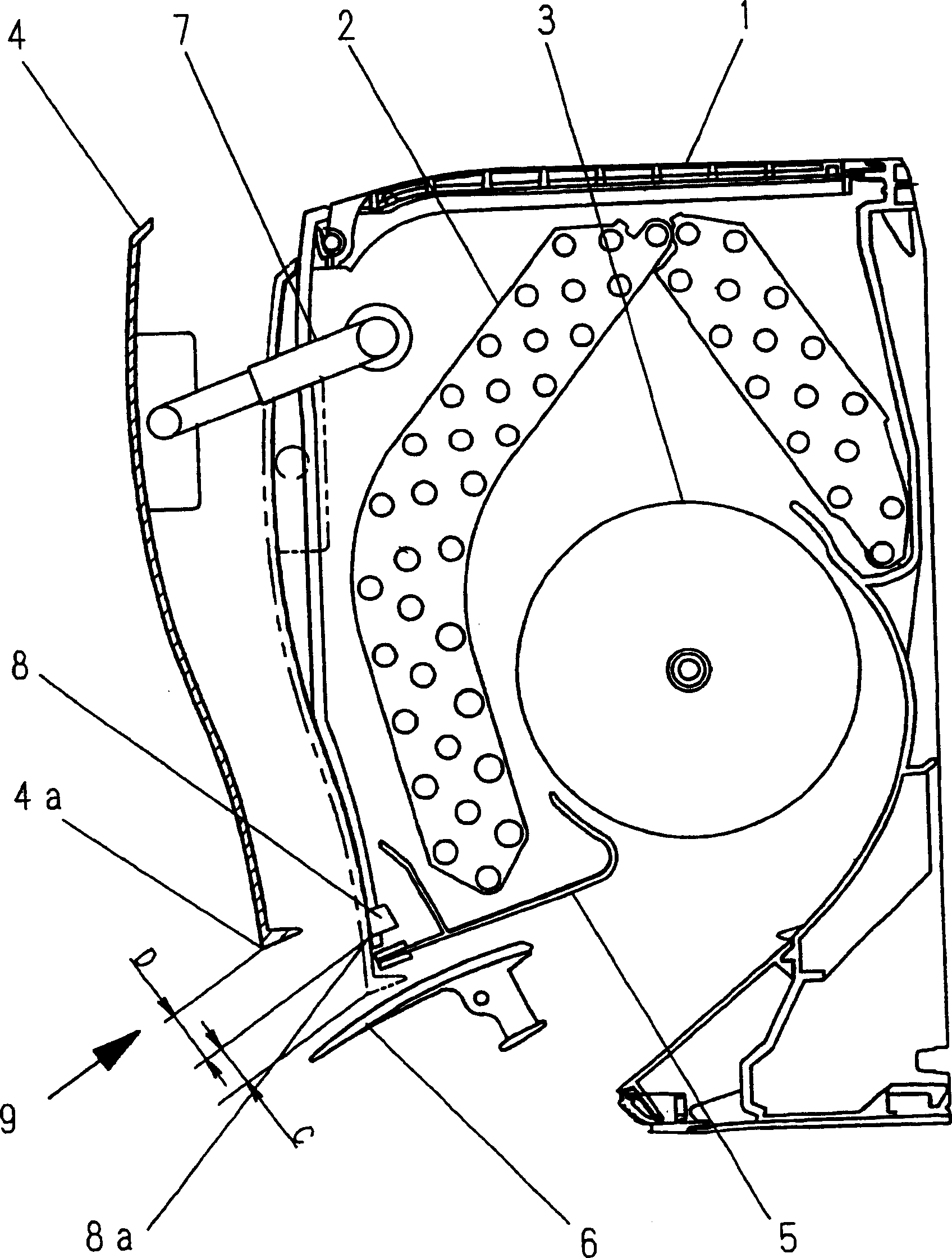
[0036] Next, use image 3 , 4 A second embodiment of the present invention will be described. In addition, the same symbols and names are used for the same parts as those in the above-mentioned embodiments, and their descriptions are omitted.
[0037] image 3 It is a cross-sectional view of the main body of the indoor unit of the air conditioner, and the front damper 4 in the open state is shown by a solid line, and the front damper 4 in the closed state is shown by a dotted line, respectively.
[0038] Figure 4 It is a front view of the main body 1 when the operation is stopped.
[0039] image 3 Among them, an indicator 8 indicating the operating state of the air conditioner is provided at the front of the water receiving pan (not shown) of the outlet grill 5 .
[0040] In addition, the above-mentioned display unit 8 is attached to a position where it cannot be seen when the main body 1 is not in operation, but can be visually recognized from the front and below duri...
Embodiment 3
[0044] Next, use Figure 5 , 6 A third embodiment of the present invention will be described. In addition, the same symbols and names are used for the same parts as those in the above-mentioned embodiments, and description thereof will be omitted.
[0045] Figure 5 It is an enlarged view of a pair of brackets 12 connecting the front panel 4 to the main body 1 and their mounting parts in a state where the front panel 4 is opened.
[0046] The bracket 12 is composed of a first support plate 14 and a second support plate 15, and the first support plate 14 has a shaft 14a for rotatably supporting its one end and the other end on the main body 1 and the front baffle 4 respectively; The second support plate 15 has a shaft 15a, which is used to rotatably set its one end and the other end on the groove-shaped or long-hole-shaped first support portion 1b formed on the main body 1 and the first support portion 1b formed on the front panel 4. In addition, the first support plate 14 ...
PUM
 Abstract
Description
Claims
Application Information
 - R&D
- Intellectual Property
- Life Sciences
- Materials
- Tech Scout
- Unparalleled Data Quality
- Higher Quality Content
- 60% Fewer Hallucinations
Browse by: Latest US Patents, China's latest patents, Technical Efficacy Thesaurus, Application Domain, Technology Topic, Popular Technical Reports.
© 2025 PatSnap. All rights reserved.Legal|Privacy policy|Modern Slavery Act Transparency Statement|Sitemap|About US| Contact US: help@patsnap.com