Treatment method and system for electroplating wastewater

A technology for electroplating wastewater and treatment system, applied in the field of electroplating wastewater treatment system and electroplating wastewater treatment, can solve the problems of incomplete nitriding treatment, low COD removal efficiency, insufficient recycling of organic matter, etc., to prevent clogging, The effect of preventing damage to the equipment

Active Publication Date: 2014-11-19
ZHEJIANG OCEAN UNIV
View PDF2 Cites 6 Cited by
  • Summary
  • Abstract
  • Description
  • Claims
  • Application Information

AI Technical Summary

Problems solved by technology

[0005] The present invention provides a treatment method and system for electroplating wastewater that can make full use of organic matter in electroplating wastewater, have thorough nitriding treatment, high COD removal efficiency, and are not prone to clogging, and solve the problem of existing electroplating wastewater The organic matter in the treatment method has not been fully recycled, the nitriding treatment is not complete, and the COD removal efficiency is low.

Method used


Image

  • Treatment method and system for electroplating wastewater
  • Treatment method and system for electroplating wastewater
  • Treatment method and system for electroplating wastewater

Examples


Embodiment 2

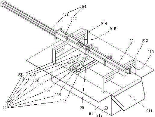
[0076] Embodiment two, see Figure 4 , the difference from Embodiment 1 is that the floating object removal device also includes an impeller 96, a delivery pipe 963, an air pump 98, an air distribution mechanism 99 and an air pipe network 916. The air cylinder constituting the telescoping mechanism 94 also includes a piston 943 . The piston 943 divides the cylinder 941 into an extension cavity 9411 and a retraction cavity 9412 . The protruding cavity 9411 is connected with one end of the first air tube 944 . The retraction cavity 9412 is connected with one end of the second air pipe 945 .

[0077] The impeller 96 includes an impeller shaft 961 and impeller blades 962 connected to the impeller shaft. The impeller blades 962 are located in the delivery tube 97 . The impeller rotating shaft 961 and the drive shaft of the air pump 98 are connected together.

[0078] The gas distribution mechanism 97 includes a moving plate 971 , a rotating shaft 972 and a motor 973 . The mov...

Embodiment 3

[0082] Embodiment three, the difference with described example two is:

[0083] see Figure 6 , The floating object removal device also includes a refueling device 99. The refueling device 99 includes an oil storage tank 991 , an oil outlet channel 992 , a membrane rupture rod 993 , a storage tank for corrosive liquid 994 , a regular rotting buoy 995 and a guide rod 996 .

[0084] The oil storage tank 991 is connected together with the regular rotting buoy 995 by a connecting rod 998 . The connecting rod 998 is detachably connected with the regular rotting buoy 995 by bolts. The oil storage tank 991 includes at least two cavities 9911 which are sequentially sheathed and fastened together in this embodiment, which are four. Lubricating oil is housed in the cavity 9911 (not drawn in the lubricating oil figure). The lower side wall of the cavity 9911 is provided with an oil outlet 9912 . The oil outlet 9912 is sealed and connected with a sealing membrane 9913. A total of 4 o...


PUM


Abstract

The invention relates to an electroplating wastewater treatment process. The invention provides a treatment method and system for electroplating wastewater by which organic substances in the electroplating wastewater are completely used, nitridation treatment is thorough, the COD removal efficiency is high, a blockage phenomenon is hardly caused, and solves problems in the existing electroplating wastewater treatment method that the organic substances are not sufficiently recycled and used, the nitridation treatment is incomplete and the COD removal efficiency is low. The method mainly comprises the steps of solid-liquid separation, suspended matter removal, heavy metal ion removal, organic substance treatment and the like. The system comprises an acid absorption tower, as well as a solid-liquid separator, a floating matter removing device and a metal ion treatment device which are in butt joint in sequence, wherein a liquid outlet of the metal ion treatment device is equipped with an anaerobic digester, an anaerobic settling tank, an ammonia stripping tower, an anoxic / oxic tank, a secondary settling tank and a sterilizing tank which are in butt joint in sequence; and the acid absorption tower and the ammonia stripping tower are connected together for absorbing ammonia gas.

Description

technical field [0001] The invention relates to an electroplating wastewater treatment process, in particular to an electroplating wastewater treatment method and an electroplating wastewater treatment system. Background technique [0002] In order to meet environmental protection requirements, electroplating wastewater needs to be treated. Electroplating wastewater mainly includes water, suspended particles, precipitable particles, heavy metal ions, ammonia nitrogen (NH 3 -N) and organic matter (COD), etc. [0003] The existing electroplating wastewater treatment method is: directly remove the heavy metal ions from the electroplating wastewater discharged from the factory through the heavy metal ion removal device, and then discharge it to the sewage treatment plant through the sewage pipe network for ammonia nitrogen (NH 3 -N) and handling of organic matter. The treatment method of electroplating wastewater is disclosed in the patent document with Chinese patent app...

Claims


Application Information

Patent Timeline
Patent Type & Authority Applications(China)
IPC IPC(8): C02F9/14C02F103/16
Inventor 童相第
Owner ZHEJIANG OCEAN UNIV
Why Eureka
Try Eureka