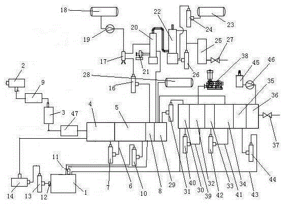
Electroplating wastewater treatment system
A treatment system, electroplating wastewater technology, applied in metallurgical wastewater treatment, water/sewage multi-stage treatment, water/sludge/sewage treatment, etc., can solve incomplete nitriding treatment, low COD removal efficiency, and insufficient organic matter Recycling and other issues to achieve the effect of preventing clogging and preventing damage to equipment
- Summary
- Abstract
- Description
- Claims
- Application Information
AI Technical Summary
Problems solved by technology
Method used
Image
Examples
Embodiment 2
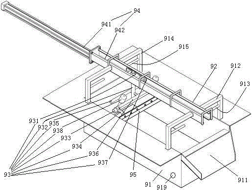
[0076] Embodiment two, see Figure 4 , the difference from Embodiment 1 is that the floating object removal device also includes an impeller 96, a delivery pipe 963, an air pump 98, an air distribution mechanism 99 and an air pipe network 916. The air cylinder constituting the telescoping mechanism 94 also includes a piston 943 . The piston 943 divides the cylinder 941 into an extension cavity 9411 and a retraction cavity 9412 . The protruding cavity 9411 is connected with one end of the first air tube 944 . The retraction cavity 9412 is connected with one end of the second air pipe 945 .
[0077] The impeller 96 includes an impeller shaft 961 and impeller blades 962 connected to the impeller shaft. The impeller blades 962 are located in the delivery tube 97 . The impeller rotating shaft 961 and the drive shaft of the air pump 98 are connected together.
[0078] The gas distribution mechanism 97 includes a moving plate 971 , a rotating shaft 972 and a motor 973 . The mov...
Embodiment 3
[0082] Embodiment three, the difference with described example two is:
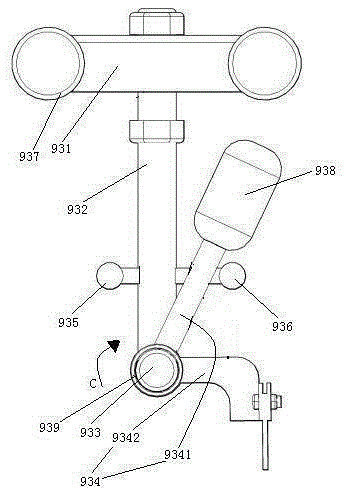
[0083] see Image 6 , The floating object removal device also includes a refueling device 99. The refueling device 99 includes an oil storage tank 991 , an oil outlet channel 992 , a membrane rupture rod 993 , a storage tank for corrosive liquid 994 , a regular rotting buoy 995 and a guide rod 996 .
[0084] The oil storage tank 991 is connected together with the regular rotting buoy 995 by a connecting rod 998 . The connecting rod 998 is detachably connected with the regular rotting buoy 995 by bolts. The oil storage tank 991 includes at least two cavities 9911 which are sequentially sheathed and fastened together in this embodiment, which are four. Lubricating oil is housed in the cavity 9911 (not drawn in the lubricating oil figure). The lower side wall of the cavity 9911 is provided with an oil outlet 9912 . The oil outlet 9912 is sealed and connected with a sealing membrane 9913. A total of 4 oi...
PUM
 Abstract
Description
Claims
Application Information
 - R&D
- Intellectual Property
- Life Sciences
- Materials
- Tech Scout
- Unparalleled Data Quality
- Higher Quality Content
- 60% Fewer Hallucinations
Browse by: Latest US Patents, China's latest patents, Technical Efficacy Thesaurus, Application Domain, Technology Topic, Popular Technical Reports.
© 2025 PatSnap. All rights reserved.Legal|Privacy policy|Modern Slavery Act Transparency Statement|Sitemap|About US| Contact US: help@patsnap.com


