Trimming device with a reel protector

一种保护器、设备的技术,应用在园艺工具/设备、切割设备、植物学设备和方法等方向,能够解决耗时更换、刚性地布置在壳体等问题

Inactive Publication Date: 2006-08-30
DOLMAR
View PDF2 Cites 4 Cited by
  • Summary
  • Abstract
  • Description
  • Claims
  • Application Information

AI Technical Summary

Problems solved by technology

[0007] It can be seen that a disadvantage of known trimming devices with a spool protector is that the shell-shaped spool protector is either rigidly arranged on the housing (eg a gearbox) or integrated into the housing
Since it should be possible to use trimming devices with different knives, which may have different thicknesses, then either the reel protector needs to be changed in a time-consuming manner, that is to say screwed onto a suitable reel protector, or the reel must be connected by inserting additional spacers. to move the existing spool protector to the desired position

Method used


Image

  • Trimming device with a reel protector
  • Trimming device with a reel protector

Examples


Embodiment Construction

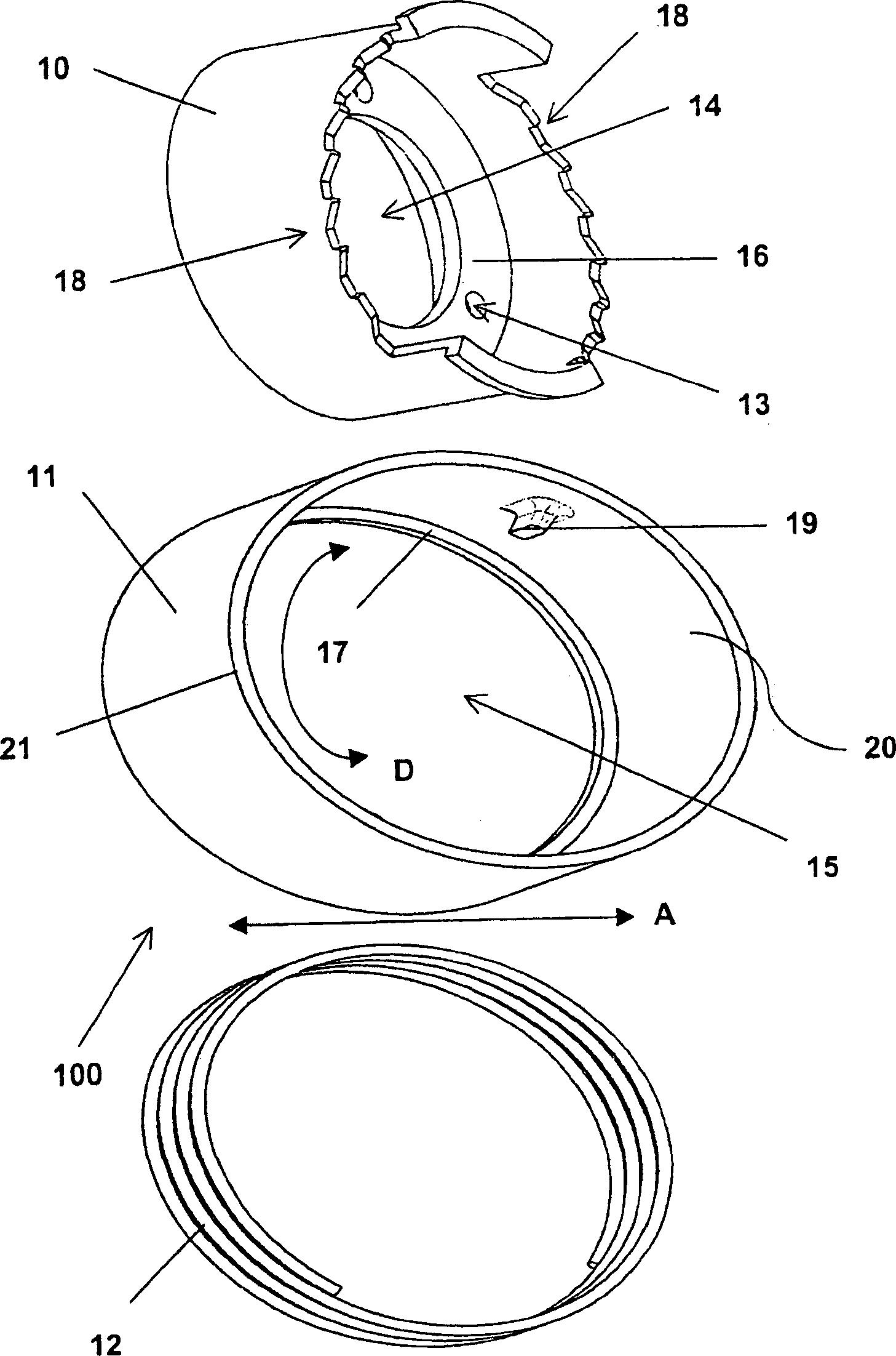
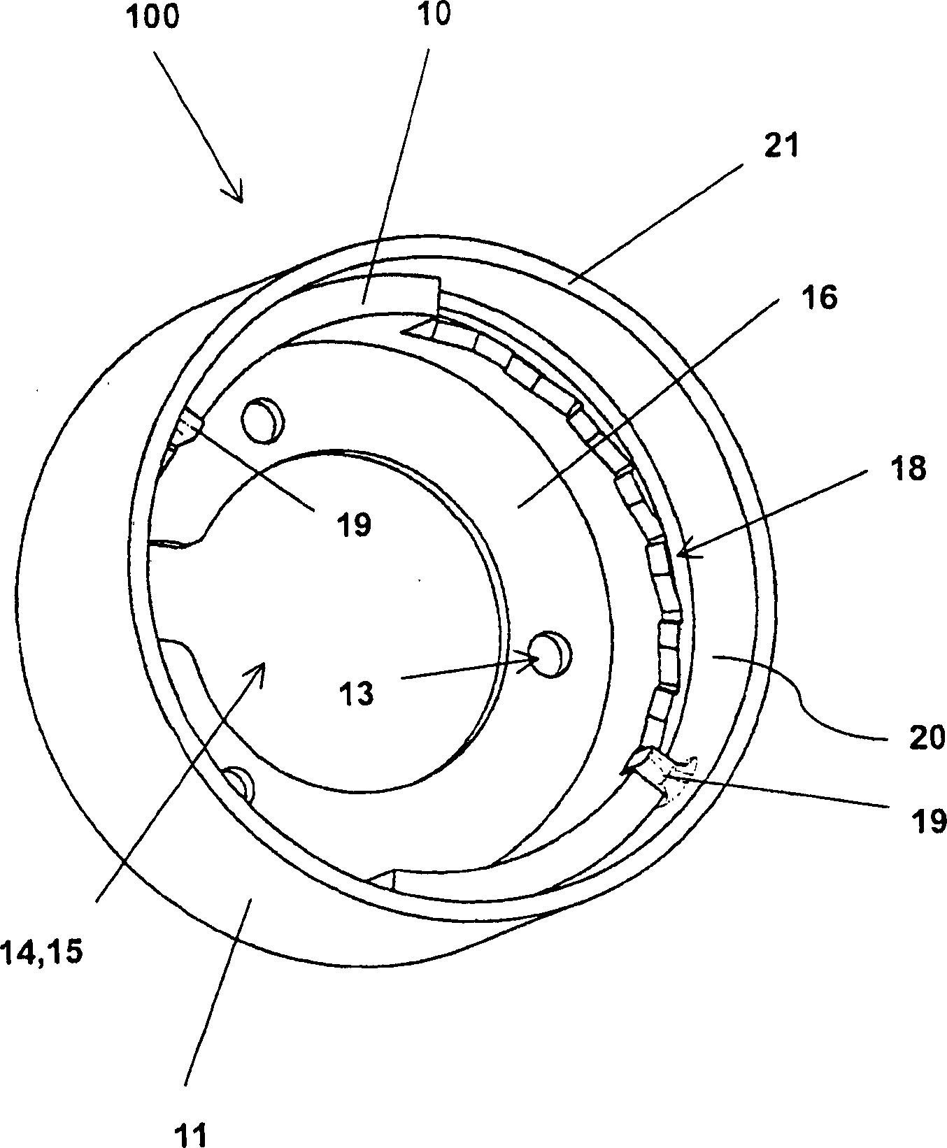
[0021] figure 1 with 2 The illustrated embodiment relates to a reel protector 100 for a finishing device, which is not shown in the drawing to simplify the drawing. The reel protector 100 is mainly composed of a first housing 10 and a second housing 11 made of metal, respectively, and a spring 12 made of elastic metal known to those skilled in the art.

[0022] The first housing 10 includes a threaded hole 13 so that it can be installed on a gear box or a motor box of a dressing device. The rotation axis of the tool extends through the first housing 10 and the second housing 11, respectively. The first housing 10 and the second housing 11 are respectively provided with openings 14, 15 for this purpose.

[0023] in figure 1 A continuous peripheral shoulder 17 protruding substantially radially inward is preferably integrally formed on the upper side of the second housing 11 on the left side. The spring 12 (such as a coil spring) is adjacent to this shoulder to apply a pressure to...


PUM


Abstract

The invention pertains to a trimming device with a motor-driven cutting tool that is rotatable about a shaft and with a shell-like reel protector ( 100 ), wherein said trimming device can be operated with different cutting tools. In order to achieve a simple adaptation of the reel protector to the respective tool used, the invention proposes that the reel protector ( 100 ) includes a first shell ( 10 ) that is rigidly connected to the trimming device and a second shell ( 11 ) that can be displaced relative to the first shell ( 10 ) in the direction (A) of the shaft of the cutting tool.

Description

Technical field [0001] The invention relates to a dressing device, which has a motor-driven cutter and a shell-shaped reel protector, and the cutter can rotate around an axis. Background technique [0002] Those skilled in the art are familiar with various embodiments of dressing devices. These dressing devices mainly include a motor for driving a tool rotatably supported on a shaft, preferably an internal combustion engine or an electric motor. The motor is preferably spaced apart from the knife and arranged in a housing with a handle that enables the user to hold and manipulate the dressing device. The drive shaft extends from the motor through a shaft tube provided on the housing to reach the tool. If so required, an intermediate gear may be provided at the end of the shaft tube so that the rotation axis of the tool is arranged substantially vertical when the shaft tube is held in the inclined position. [0003] In particular, a saw blade, a serrated knife, or a rotary dressin...

Claims


Application Information

Patent Timeline
Patent Type & Authority Applications(China)
IPC IPC(8): A01G3/053A01G3/033A01G3/06A01D75/18A01D34/412B26B19/14
CPCY10T83/9464A01D34/90A01D34/416A01D75/18
Inventor M·耶瑟
Owner DOLMAR
Why Eureka
Try Eureka