Angular adjustment accessory

An angle adjustment and parts technology, applied in the field of angle adjustment parts, can solve the problems of inability to perform fine adjustment, inability to claws, small gears, and few angle switching stages, etc. Effect

Inactive Publication Date: 2006-08-30
山下 直伸
View PDF0 Cites 6 Cited by
  • Summary
  • Abstract
  • Description
  • Claims
  • Application Information

AI Technical Summary

Problems solved by technology

That is, due to the necessary strength, the claws and gears cannot be made smaller
[0005] Therefore, the housing for housing the claws and the gears is relatively large. In

Method used


Image

  • Angular adjustment accessory
  • Angular adjustment accessory
  • Angular adjustment accessory

Examples


Embodiment Construction

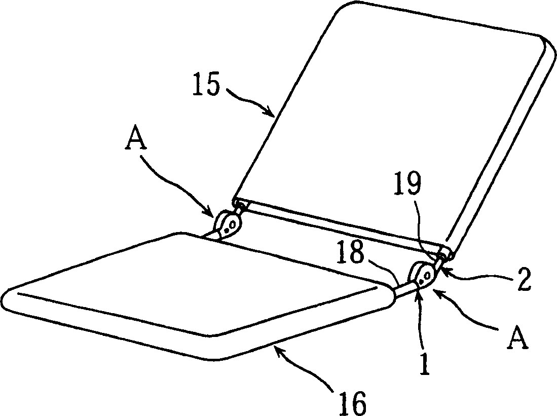
[0038] Angle adjustment parts of the present invention, such as figure 1 As shown in the perspective view, it is a part that is arranged between the backrest 15 and the seat portion 16 so that the inclination angle of the backrest 15 can be adjusted on the seat with the backrest 15 and the seat portion 16 . That is, the angle adjustment part A is a joint part (connection part) having an angle adjustment function. In addition, this part A can be used not only on the seat, but also on sofas, headrests, footrests, etc. Shelves etc. with doors swinging open and close.

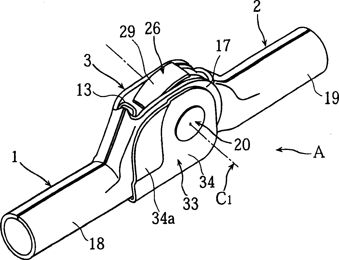
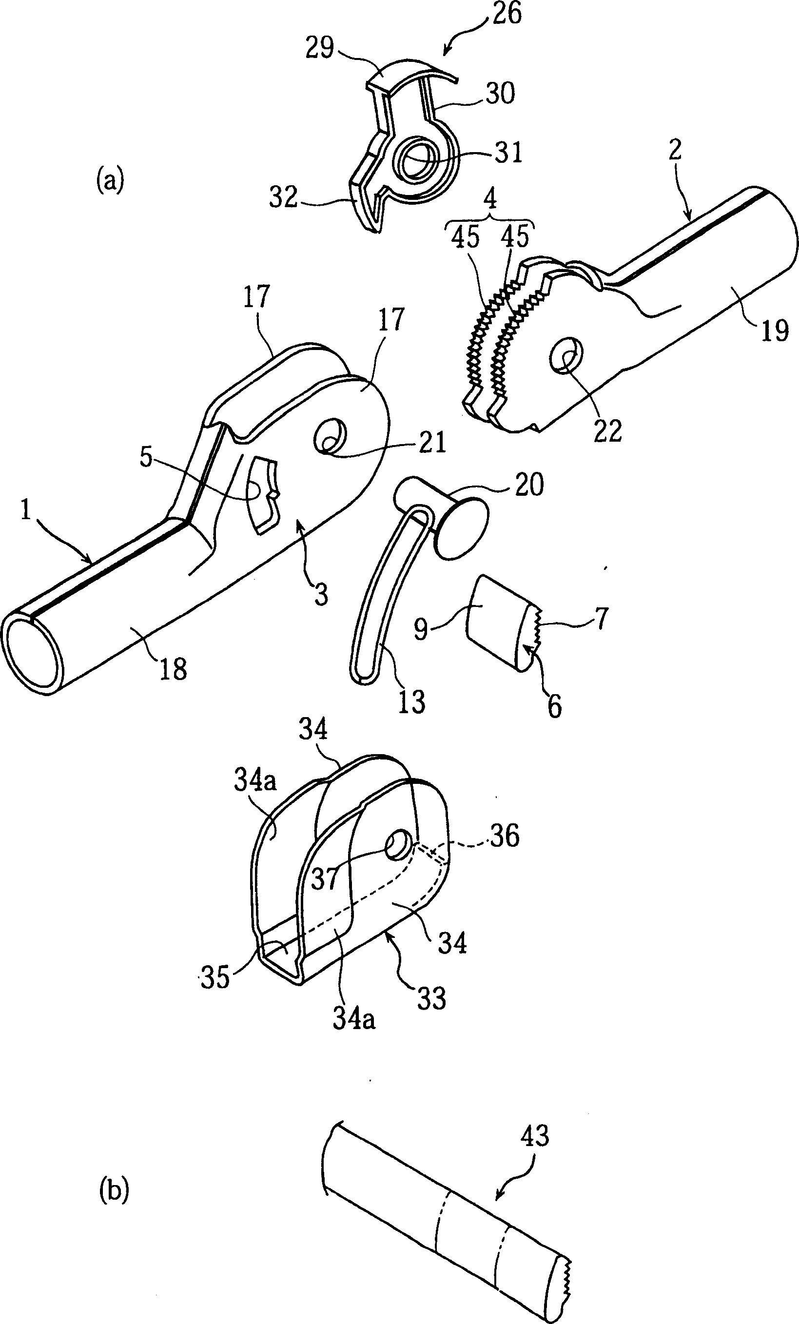
[0039] figure 2 is a perspective view of the angle adjustment part A, image 3 is its exploded perspective view.

[0040] The angle adjustment part A of the present invention has: a first arm 1 with a shell portion 3; 1 The swinging way is pivotally connected with the first arm 1, and has a first axis C 1 Centered gear part 4. That is, the first arm 1 and the second arm 2 are pivotally mounted so that the f...


PUM


Abstract

An angle-adjustable hinge provided with a first arm having a case portion and a second arm connected to the first arm with the case portion as to oscillate around a first axis and having a gear portion. The angle-adjustable hinge is also provided with a wedge-shaped window portion formed on the case portion of the first arm. Further, the angle-adjustable hinge is also provided with a floating wedge member, disposed as to move within the wedge-shaped window portion, having one face side as a toothed face to engage with the gear portion and another face side as a contact face to contact a wedge face on an outer side of the wedge-shaped window portion. And, the second arm is composed of a plate body, having symmetrical two gear plate portions, bent as the gear plate portions become parallel with a predetermined interval.

Description

technical field [0001] The present invention relates to an angle adjustment component as a joint member which can arbitrarily set the angle formed by one member and the other member. Background technique [0002] For example, if figure 1 The seat with backrest 15 and seat portion 16 shown in the perspective view is provided with parts with angle adjustment function—angle adjustment part A between backrest 15 and seat portion 16, so that the inclination angle of backrest 15 can be adjusted. [0003] The existing parts are constructed in such a way that the gears and pawls of the second arm on the other side (the backrest 15 side) are pivotally supported in the shell of the first arm connected to one side (the seat portion 16 side). The claw piece is engaged with the gear to suppress swinging of the second arm relative to the first arm in the unfolding direction (the direction in which the backrest 15 falls down) (for example, refer to Patent Document 1). [0004] The force ...

Claims


Application Information

Patent Timeline
IPC IPC(8): A47C7/00A47C1/024
Inventor 山下直伸
Owner 山下 直伸
Why Eureka
Try Eureka