Magnetoresistance brushless multi-polar rotation transformer

A resolver and reluctance technology, which is applied in the direction of transformers, inductors, electrical components, etc., can solve the problems of complex structure of resolver and inapplicability of multi-pole angle measurement with a small number of pole pairs.

Inactive Publication Date: 2006-08-30
HARBIN INST OF TECH
View PDF0 Cites 28 Cited by
  • Summary
  • Abstract
  • Description
  • Claims
  • Application Information

AI Technical Summary

Problems solved by technology

[0003] In order to solve the problem that the existing rotary transformer used for angle measurement has a complex structure and is not suitable for multi-pole angle measurement with a small number of pole

Method used


Image

  • Magnetoresistance brushless multi-polar rotation transformer
  • Magnetoresistance brushless multi-polar rotation transformer
  • Magnetoresistance brushless multi-polar rotation transformer

Examples


specific Embodiment approach 1

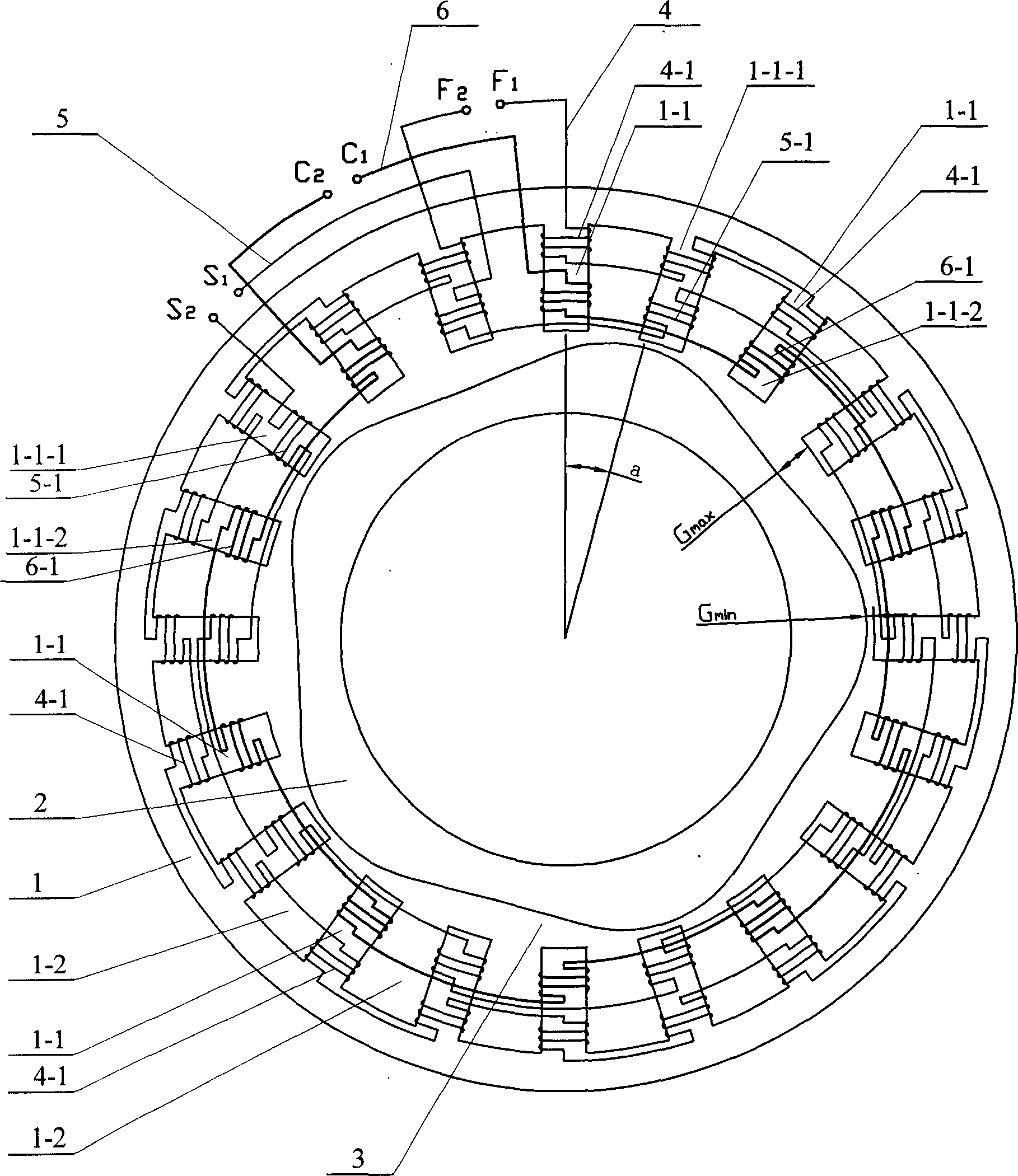
[0014] Specific implementation manner one: such as figure 1 As shown, the resolver of this embodiment is composed of a rotor 2, a stator 1, a first coil 4-1, a second coil 5-1, and a third coil 6-1. The outer surface of the rotor 2 and the stator 1 An air gap 3 is provided between the inner circular surfaces of the rotor 2; the outer circular surface of the rotor 2 is uniformly provided with P crests and P troughs, and the crests and troughs are smoothly connected to each other to form the wavy outer circular surface of the rotor 2, wherein , P is the number of pole pairs of the resolver; the inner circular surface of the stator 1 is provided with a plurality of through slots 1-2 along the axial direction, and there are convex teeth 1- between the two adjacent through slots 1-2. 1. The inner circular surface of the stator 1 is uniformly arranged with 4P convex teeth 1-1 along the circumferential direction, and the 4P convex teeth 1-1 are sequentially divided into 2P odd convex tee...

specific Embodiment approach 2

[0015] Specific implementation manner two: such as figure 1 As shown, the difference between this specific embodiment and the first embodiment is that the stator 1 and the rotor 2 are formed by superimposing a plurality of punched pieces of electrical steel. Other components and connection relationships are the same as in the first embodiment.

specific Embodiment approach 3

[0016] Specific implementation manner three: such as figure 1 As shown, the difference between this specific embodiment and the first embodiment is that the number of turns of the second coil 5-1 and the third coil 6-1 is the same. Other components and connection relationships are the same as in the first embodiment.


PUM


Abstract

The invention relates to a reluctance brushless multipolar rotational transformer. And the external circular surface of a rotor is uniformly provided with P wave crests and P wave throughs, where these wave crests and wave throughs are smoothly interlinked to compose the wavy external circular surface of the rotor, and excitation, sine and cosine windings are positive phase-to-negative phase connected in series. As a constant voltage alternating current passes through the excitation winding, the sine and cosine windings output voltages whose electromotive force amplitudes make p sine and cosine variations with the rotation angle of the rotor. And the invention has characters of simple structure, convenient to make, and especially applied to the rotor position sensor of a brushless DC motor.

Description

Technical field [0001] The invention relates to a reluctance type brushless multi-pole rotary transformer. Background technique [0002] The traditional resolver used for angle measurement, its input and output windings are respectively placed on the rotor and stator. In order to achieve brushlessness, a coupling transformer needs to be added to make the structure more complicated; while the other vernier resolver has two windings They are all on the stator, and they are brushless, but this type of resolver has a large number of pole pairs P (for example, P is 32 or more), and a sinusoidal winding with a complicated structure is used. These two types of resolvers are not ideal components when used for multi-pole angle measurement with a small number of pole pairs, especially when used in a brushless DC motor rotor position sensor. Summary of the invention [0003] In order to solve the problem that the existing resolver for angle measurement is complicated in structure and not s...

Claims


Application Information

Patent Timeline
IPC IPC(8): H01F38/18
Inventor 陆永平孙立志邹继斌李勇刘彦彬
Owner HARBIN INST OF TECH
Why Eureka
Try Eureka