
Method of path selecting in intelligent optical network

An intelligent optical network and path selection technology, which is applied in the direction of data exchange, electrical components, and transmission systems through path configuration, and can solve the problem of not being able to find the optimal path that separates the two links as much as possible.

Inactive Publication Date: 2006-08-30
HUAWEI TECH CO LTD
View PDF0 Cites 28 Cited by
  • Summary
  • Abstract
  • Description
  • Claims
  • Application Information

AI Technical Summary

Problems solved by technology

[0007] The object of the present invention is to provide a method for path selection in an intelligent optical network, and a method for selecting two optimal paths in which links are separated as much as possible in an intelligent optical network, so as to solve the problem that two paths cannot be found in an existing intelligent optical network. The problem of the optimal path for separating links as much as possible

Method used


Image

  • Method of path selecting in intelligent optical network
  • Method of path selecting in intelligent optical network
  • Method of path selecting in intelligent optical network

Examples


Embodiment Construction

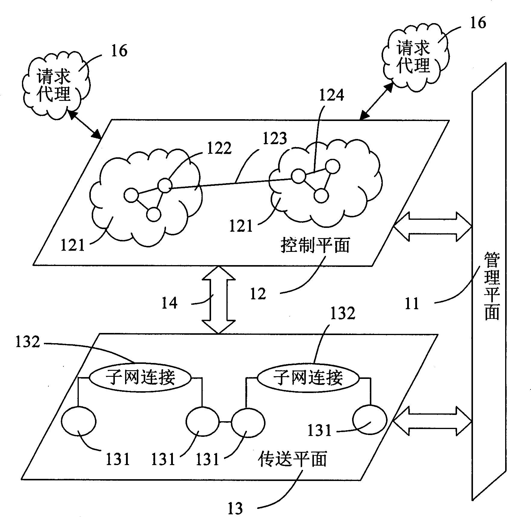
[0057] like image 3 As shown, the intelligent optical network is composed of three logical planes, that is, the transmission plane 13 , the control plane 12 and the management plane 11 . The control plane 12 and the transmission plane 13 are respectively connected to the management plane 11 , and the control plane 12 and the transmission plane 13 are connected through a connection control interface 14 .

[0058] The transport plane 13 is composed of transport network elements 131 as switching entities, which are interconnected via subnetwork connections 132 . The transmission plane 13 mainly completes functions such as connection / disconnection, switching (routing) and transmission to provide bidirectional or unidirectional information transmission from one endpoint to another, as well as some control and network management information.

[0059] The control plane 12 implements functions such as call control and connection control in the intelligent optical network. The contr...


PUM


Abstract

This invention relates to a method for path selection in an intelligent optical network including: a, clearing a first and a second storage units and putting the source node in the first storage unit, b, putting a node with the least cost relative to the source node in the first unit into the second storage unit, c, if said node is a target one, then step d is carried out, otherwise, an adjacent node meeting the restrain condition and its corresponding path are put in the first unit, d, judging if the first one is empty, e, if it is not empty, step b is carried out, otherwise, judging if the target node is in the second storage unit, if so, then the path in the second unit is the shortest one.

Description

technical field [0001] The invention relates to an intelligent optical network self-healing technology, in particular to a path selection method in an intelligent optical network. Background technique [0002] Based on the mesh network (MESH) structure, the intelligent optical network can provide a variety of service protection and recovery strategies, such as 1+1 dedicated protection, 1:N shared protection, preset path protection, complete rerouting protection, etc. Among them, 1+1 dedicated protection is an end-to-end service protection method with the highest protection strength. [0003] 1+1 dedicated protection is to use a dedicated path (protection path) to protect another path (working path). Under normal circumstances, services are transmitted on both the working path and the protection path at the same time, and the egress node in the service direction selectively receives services on the working path; when the working path fails, the egress node in the service dir...

Claims


Application Information

Patent Timeline
Patent Type & Authority Applications(China)
IPC IPC(8): H04L12/28H04L29/04H04L69/14
Inventor 冯俊杰王彧吴文鑫
Owner HUAWEI TECH CO LTD
Learn More