Image forming apparatus

A technology of imaging equipment and channels, which is applied in cleaning devices, conveyor objects, printing, etc., can solve the problem of not being able to clear the ink on the conveyor belt, and achieve a roughly uniform supply effect

Inactive Publication Date: 2006-09-06
BROTHER KOGYO KK
View PDF1 Cites 4 Cited by
  • Summary
  • Abstract
  • Description
  • Claims
  • Application Information

AI Technical Summary

Problems solved by technology

This creates the problem of not being ab

Method used


Image

  • Image forming apparatus
  • Image forming apparatus
  • Image forming apparatus

Examples


Embodiment Construction

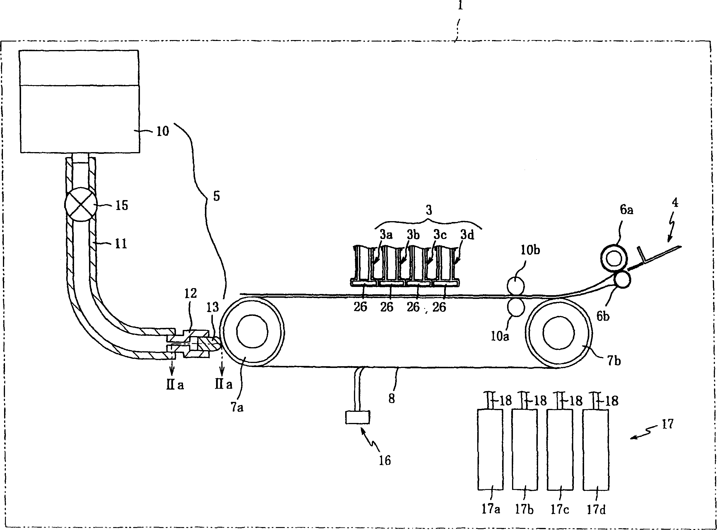
[0036] Preferred embodiments of the present invention are described below with reference to the accompanying drawings. figure 1 is a schematic diagram showing the internal structure of an inkjet printer 1 (hereinafter referred to as "printer 1") functioning as the image forming apparatus of the present invention. The printer 1 is a color inkjet printer having a head unit 3 . The head unit 3 includes four recording heads 3 a to 3 d corresponding to inks of four colors including cyan, magenta, yellow, and black.

[0037] Each of the recording heads 3a to 3d is formed in a substantially rectangular shape in cross-sectional view, and extends in the width direction perpendicular to the conveyance direction of the recording medium. These recording heads are arranged and positioned close to each other. Also, each of the recording heads 3a to 3d has a head body 26 at its lower end. Each head body 26 extends in the width direction perpendicular to the conveying direction of the reco...


PUM


Abstract

Cleaning liquid stored in a first storage tank (10) is absorbed by a sponge (13) via a passage formed in a tube (11) and a holder (12), and then applied onto a conveyance belt (8) when the sponge (13) comes into contact with the conveyance belt (8). Here, even when air bubbles enter into the cleaning liquid supplied to the sponge (13), the air bubbles are discharged to the outside through an air discharging hole formed in the holder (12).

Description

technical field [0001] SUMMARY OF THE INVENTION It is an object of the present invention to provide an image forming apparatus capable of reliably applying a cleaning solution to a conveying belt. Background technique [0002] In the prior art, there is known an image forming apparatus that ejects ink from nozzles perforated in a recording head to a recording medium placed on a conveyance belt, thereby forming an image on the recording medium. This type of image forming apparatus has a problem in that, for example, when performing borderless printing, ink can adhere to a conveyance belt conveying a recording medium, and then the adhered ink can be transferred to the recording medium. [0003] In order to solve this problem, for example, Japanese Laid-Open Patent Application No. 2004-196505 discloses a technique of connecting a container for storing a cleaning liquid to an absorbent body through a tube so that the cleaning liquid is absorbed from the container to the absorber...

Claims


Application Information

Patent Timeline
IPC IPC(8): B41J29/17B41J2/01B65G45/22
CPCB41J29/17B41J11/007
Inventor 中岛笃久
Owner BROTHER KOGYO KK
Why Eureka
Try Eureka