Reformer

a technology of reformer and reformed raw fuel, which is applied in the field of reformer, can solve the problems of inability to supply a reformed raw fuel stably, difficult to meet the minimum flow velocity requirements, and absorb raw fuel pulsation flows, etc., and achieves the effect of maintaining the desired reforming efficiency, small size and simple structur

Active Publication Date: 2011-07-07
HONDA MOTOR CO LTD
View PDF4 Cites 29 Cited by
  • Summary
  • Abstract
  • Description
  • Claims
  • Application Information

AI Technical Summary

Benefits of technology

[0010]It is an object of the present invention to provide a reformer which is simple in structure and small in size, is capable of maintaining a desir

Problems solved by technology

However, the reformer disclosed in Japanese Laid-Open Patent Publication No. 2006-273635 finds it difficult to meet minimum flow velocity requirements and tends to fail to prevent uneven flow distribution of the fuel gas, in a wide operating range.
In addition, the disclosed reformer cannot absorb pulsation flows of raw fuel and hence cannot supply a reformed raw fuel stably.
If the desulfurizer disclosed in Japanese Laid-Open

Method used


Image

  • Reformer
  • Reformer
  • Reformer

Examples


first embodiment

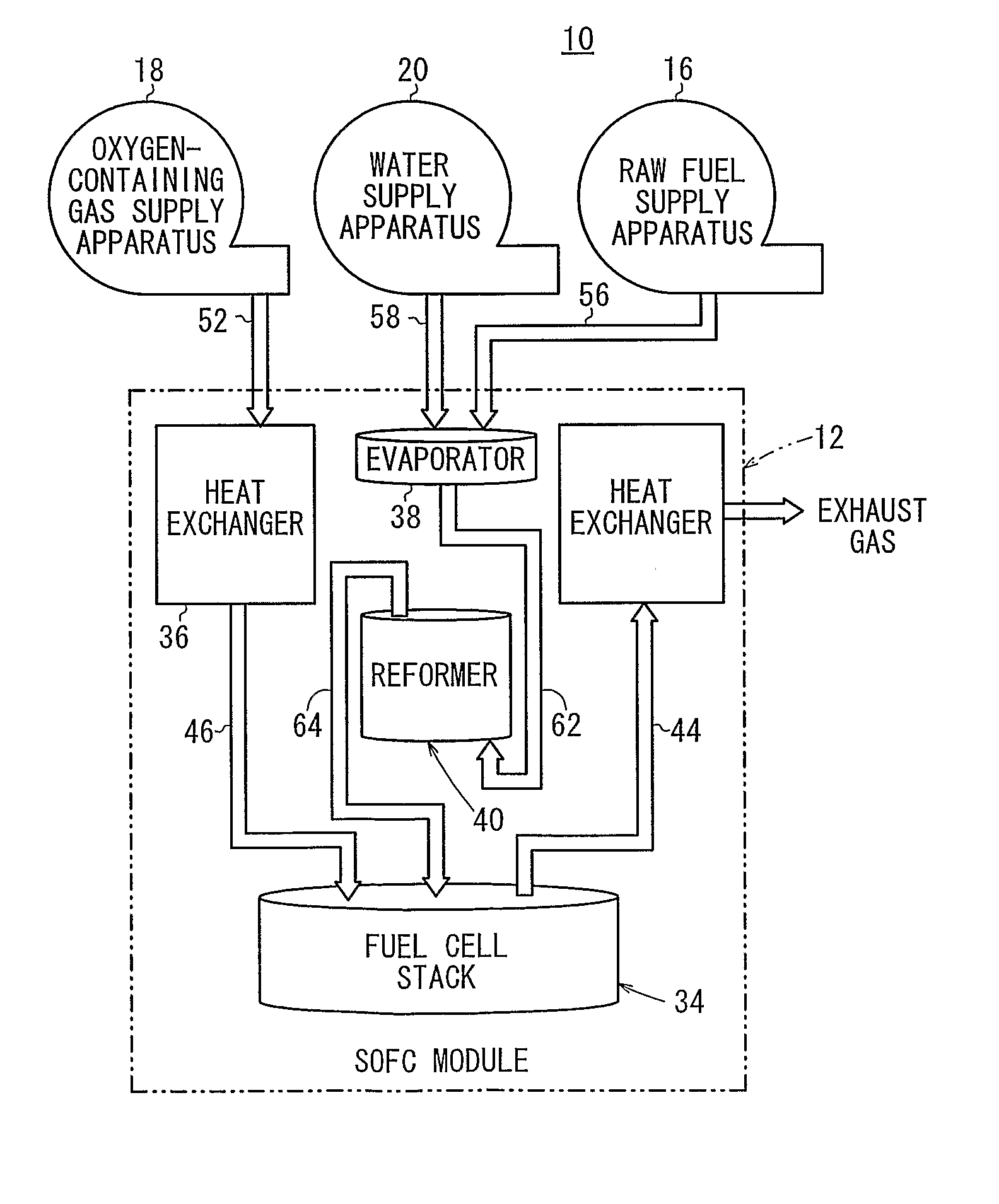
[0038]As shown in FIG. 1, a fuel cell system 10 which incorporates a reformer according to the present invention is used in various applications, e.g., used as a stationary fuel cell system, a vehicle-mounted fuel cell system, or the like.

[0039]The fuel cell system 10 comprises a fuel cell module (SOFC module) 12 for generating electrical energy in power generation by electrochemical reactions of a fuel gas (hydrogen gas) and an oxygen-containing gas (air), a raw fuel supply apparatus 16 for supplying a raw fuel, e.g., a city gas, to the fuel cell module 12, an oxygen-containing gas supply apparatus 18 for supplying the oxygen-containing gas to the fuel cell module 12, and a water supply apparatus 20 for supplying water to the fuel cell module 12.

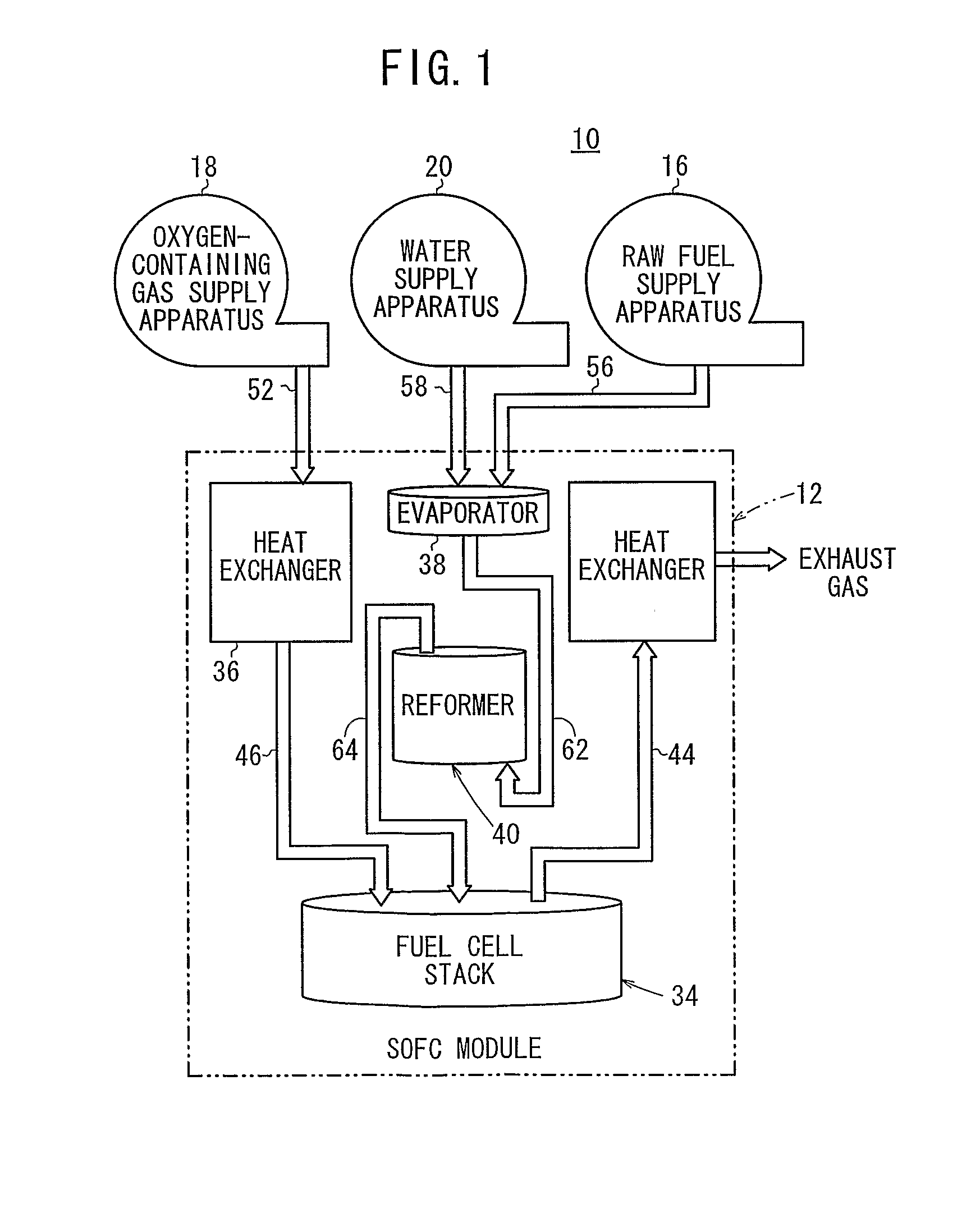
[0040]As shown in FIG. 2, the fuel cell module 12 includes a fuel cell stack 34 formed by stacking a plurality of solid oxide fuel cells 32 in a vertical direction. The fuel cells 32 are formed by stacking electrolyte electrode assemblies 2...

second embodiment

[0089]FIG. 6 is a perspective view of a reformer 90 according to the present invention. FIG. 7 is a sectional plan view of the reformer 90. FIG. 8 is a schematic diagram showing an expanded representation of a raw fuel passage in the reformer 90.

[0090]Those parts of the reformer 90 which are identical to those of the reformer 40 according to the first embodiment are denoted by identical reference characters, and will not be described in detail below. Similarly, those parts of reformers according to third through seventh embodiments to be described below which are identical to those of the reformer 40 according to the first embodiment are denoted by identical reference characters, and will not be described in detail below.

[0091]As shown in FIG. 7, the reformer 90 comprises a hollow cylindrical tubular body 70 which houses therein a plurality of partition plates 92a through 92g extending from the center of the tubular body 70 radially outwardly to the inner circumferential surface of ...

third embodiment

[0101]FIG. 9 is a perspective view of a reformer 100 according to the present invention, and FIG. 10 is a sectional side elevational view of the reformer 100.

[0102]As shown in FIGS. 9 and 10, the reformer 100 includes a box-shaped casing 102 having a supply chamber 78 defined in a lower portion near one end thereof and held in fluid communication with a supply port 72a on the lower end of the casing 102, and a discharge chamber 80 defined in an upper portion near the other end thereof and held in fluid communication with a discharge port 72b on the upper end of the casing 102. The casing 102 defines therein a reforming chamber 76 including a raw fuel passage 104 which has a first reverser 104a and a second reverser 104b for reversing the direction in which the raw fuel flows.

[0103]The casing 102 includes partition plates 106a, 106b disposed therein. The first reverser 104a is formed by cutting off an upper end portion of the partition plate 106a, and the second reverser 104b is form...


PUM


Abstract

A reformer includes a reforming chamber having a raw fuel passage through which a raw fuel flows, the reforming chamber being filled with or carrying a reforming catalyst, a supply chamber disposed upstream of the reforming chamber, for uniformly supplying the raw fuel to the raw fuel passage, and a discharge chamber disposed downstream of the reforming chamber, for uniformly discharging the raw fuel from the raw fuel passage. The raw fuel passage has first and second reversers for reversing the direction in which the raw fuel flows. The raw fuel passage has a cross-sectional area which is smaller in a downstream portion thereof than in an upstream portion thereof.

Description

TECHNICAL FIELD[0001]The present invention relates to a reformer for reforming a raw fuel which primarily contains hydrocarbon.BACKGROUND ART [0002]Typically, a solid oxide fuel cell (SOFC) employs a solid electrolyte comprising ion-conductive solid oxide such as stabilized zirconia, for example. The electrolyte is interposed between an anode and a cathode to form an electrolyte electrode assembly. The electrolyte electrode assembly is interposed between separators (bipolar plates). In use, normally, predetermined numbers of the electrolyte electrode assemblies and the separators are stacked together to form a fuel cell stack.[0003]As the fuel gas supplied to the fuel cell, normally, a hydrogen gas generated from hydrocarbon raw material by a reformer is used. In general, in the reformer, a reformed raw material gas is obtained from hydrocarbon raw material of a fossil fuel or the like, such as methane or LNG, and the reformed raw material gas undergoes steam reforming, partial oxid...

Claims


Application Information

Patent Timeline
IPC IPC(8): H01M8/06B01J19/00
CPCB01J8/0085Y02E60/525B01J8/0484B01J8/0496B01J19/249B01J2208/00132B01J2208/00203B01J2208/00309B01J2208/00504B01J2208/0053B01J2219/1923B01J2219/2453B01J2219/2455B01J2219/2458B01J2219/2462B01J2219/2481C01B3/384C01B2203/0233C01B2203/066C01B2203/0805C01B2203/1241C01B2203/1247C01B2203/1276C01B2203/1288C01B2203/1294H01M8/0618H01M2008/1293Y02E60/523Y02E60/50B01J8/009
Inventor YAMAMOTO, JUNKIYOHIRO, YUKIHIKO
Owner HONDA MOTOR CO LTD
Why Eureka
Try Eureka