Combined laundry machine

a laundry machine and laundry technology, applied in other washing machines, laundry driers, textiles and paper, etc., can solve the problems of excessive energy consumption, inefficient energy saving aspect, and drum type drying machine not suitable for drying shoes, etc., to achieve effective drying, effective drying, and smooth circulation of hot air

Inactive Publication Date: 2008-03-06
LG ELECTRONICS INC
View PDF7 Cites 30 Cited by
  • Summary
  • Abstract
  • Description
  • Claims
  • Application Information

AI Technical Summary

Benefits of technology

[0037] Preferably, each shelf is mounted in an inclined fashion. More preferably, the shelf is inclined downward toward the region where air is introduced. In this case, hot air is uniformly supplied to the laundry placed on the shelf, and therefore, the laundry is effectively dried.
[0038] When the shelf is inclined as described above, water contained in each shoe flows downward and is collected in the lower part of the shoe, and therefore, the shoe is more effectively dried.
[0039] When the shelf is inclined as described above, on the other hand, the introduced hot air collides with the shelf and flows downward through the through-holes of the shelf, and therefore, the circulation of hot air is smoothly accomplished.
[0040] Preferably, each drawer is provided at the rear wall thereof with an air guide for guiding air to the upper part of the drawer. In this case, the air, introduced into the upper part of the rear wall of the drawer, is not directed downward but is guided to an object to be dried. Consequently, the drying operation is more effectively performed.

Problems solved by technology

However, the large-sized laundry treating apparatuses are operated even to dry a small quantity of laundry, with the result that energy consumption is excessively increased.
Consequently, the drum type drying machine is not suitable for drying shoes.
Consequently, it is very inefficient in an energy saving aspect.
However, conventional washing-related systems have come into the market very restrictively.

Method used


Image

  • Combined laundry machine
  • Combined laundry machine
  • Combined laundry machine

Examples


Embodiment Construction

[0048] Reference will now be made in detail to the preferred embodiments of the present invention, examples of which are illustrated in the accompanying drawings. Wherever possible, the same reference numbers will be used throughout the drawings to refer to the same or like parts.

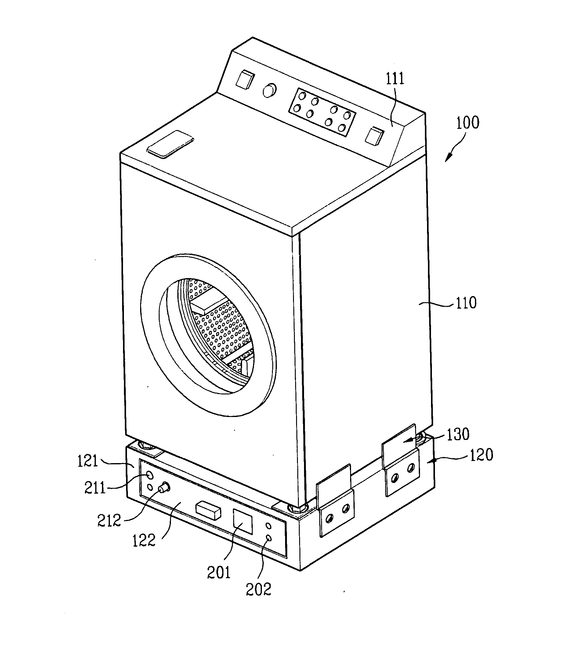
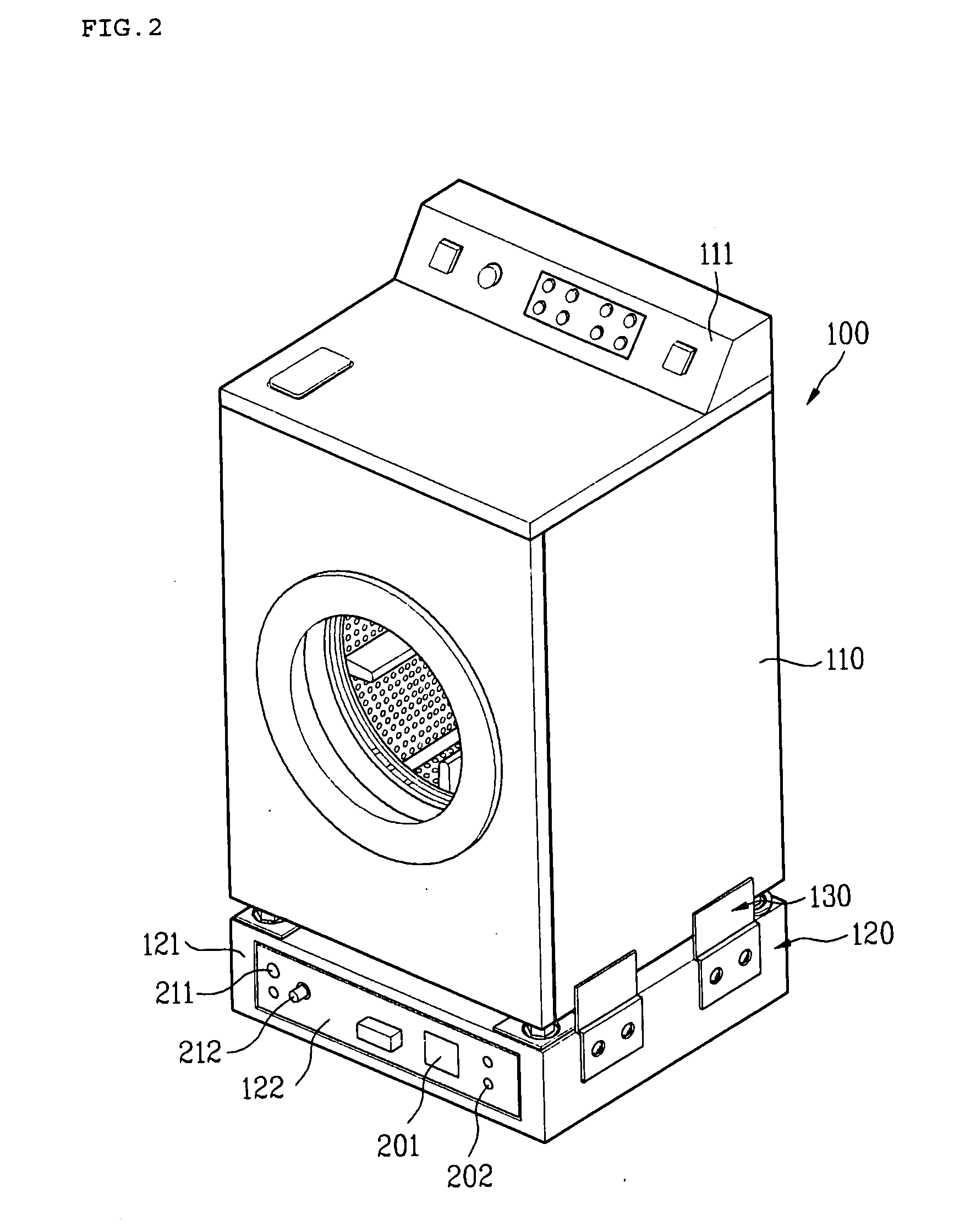
[0049] First, a combined laundry machine according to the present invention, especially a clothes dryer 100 and a second pedestal dryer 120 of the combined laundry machine, will be described below in detail with reference to FIGS. 2 to 4.

[0050] A first pedestal dryer of the combined laundry machine is not very different from the second pedestal dryer 120, and therefore, the details of the first pedestal dryer will not be given because the overall structure of the first pedestal dryer can be fully understood from the following description of the second pedestal dryer 120.

[0051] As shown in FIG. 2, the second pedestal dryer 120 serves as a base for supporting a main body 110 of the clothes dryer 100.

[0052...


PUM


Abstract

A combined laundry machine including a new conceptional pedestal dryer that is capable of performing a drying operation while serving as a base for supporting a washer or a dryer is disclosed. The combined laundry machine includes a washer, a first pedestal dryer including a first container for supporting the washer, the first container having a drying space for drying an object to be dried using hot air supplied from a first hot air supply unit, a clothes dryer, and a second pedestal dryer including a second container for supporting the clothes dryer, the second container having a drying space for drying an object to be dried using hot air supplied from a second hot air supply unit.

Description

CROSS-REFERENCE TO RELATED APPLICATION [0001] This application claims the benefit of Korean Patent Application No. 10-2006-0082283, filed on Aug. 29, 2006, which is hereby incorporated by reference in its entirety as if fully set forth herein. BACKGROUND OF THE INVENTION [0002] 1. Field of the Invention [0003] The present invention relates to a combined laundry machine, and more particularly, to a combined laundry machine including a new conceptional pedestal dryer that is capable of performing a drying operation while serving as a base for supporting a washer or a dryer. [0004] 2. Discussion of the Related Art [0005] Generally, laundry treating apparatuses are electric home appliances that are capable of washing and / or drying laundry. Specifically, the respective laundry treating apparatuses perform a washing operation, a drying operation, or a washing-and-drying operation. Recently, there has been increasingly used a laundry treating apparatus, including a steam supply unit, that ...

Claims


Application Information

Patent Timeline
Patent Type & Authority Applications(United States)
IPC IPC(8): D06F29/00
CPCD06F39/125D06F58/10D06F58/18D06F58/26D06F2103/56D06F2105/28D06F2105/30
Inventor PARK, SANGLEE, PHAL
Owner LG ELECTRONICS INC
Why Eureka
Try Eureka