Gas fuel catalytic combustor

A catalytic burner, gas fuel technology, applied in the directions of gas fuel burners, burners, combustion methods, etc., can solve the problems of small application range of catalytic combustion stoves and high NOx emissions

Inactive Publication Date: 2006-09-06
BEIJING UNIV OF TECH
View PDF0 Cites 21 Cited by
  • Summary
  • Abstract
  • Description
  • Claims
  • Application Information

AI Technical Summary

Problems solved by technology

[0005] The purpose of the present invention is to solve the problems of high NOx emission existing in existing b

Method used


Image

  • Gas fuel catalytic combustor
  • Gas fuel catalytic combustor
  • Gas fuel catalytic combustor

Examples


Embodiment Construction

[0019] Preferred embodiments of the present invention will now be described in detail with reference to the accompanying drawings.

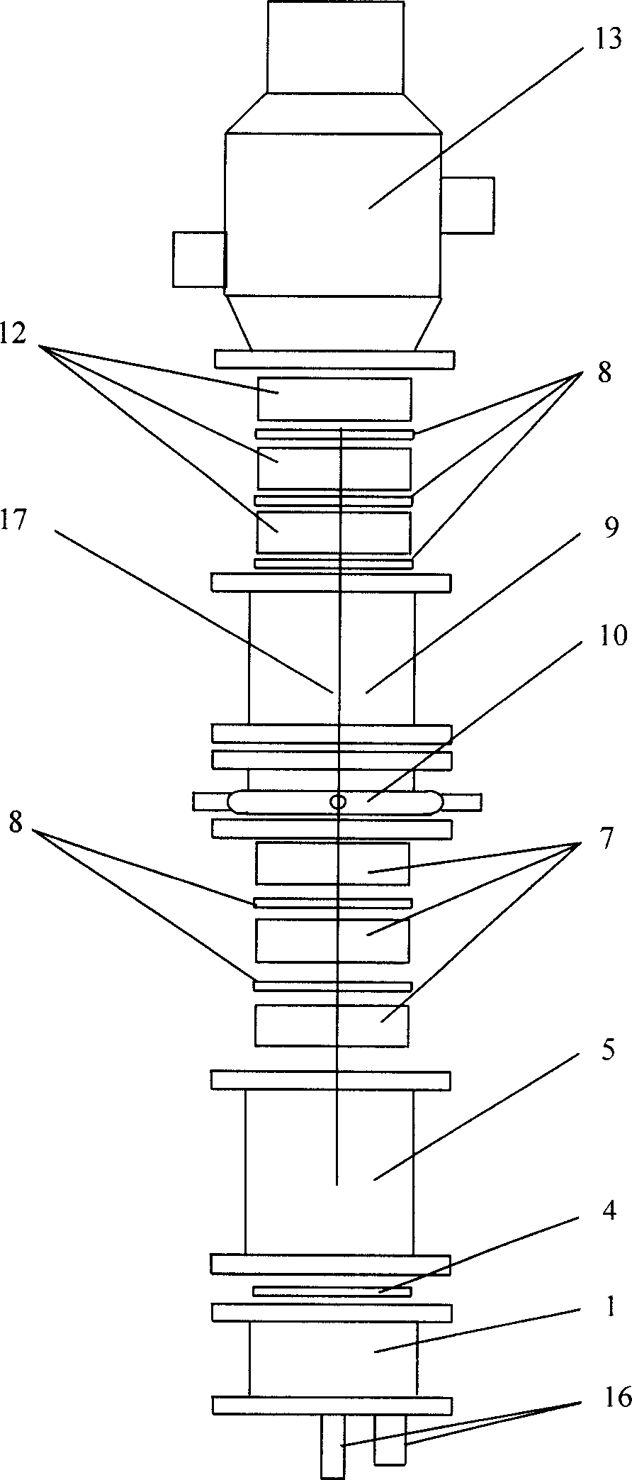
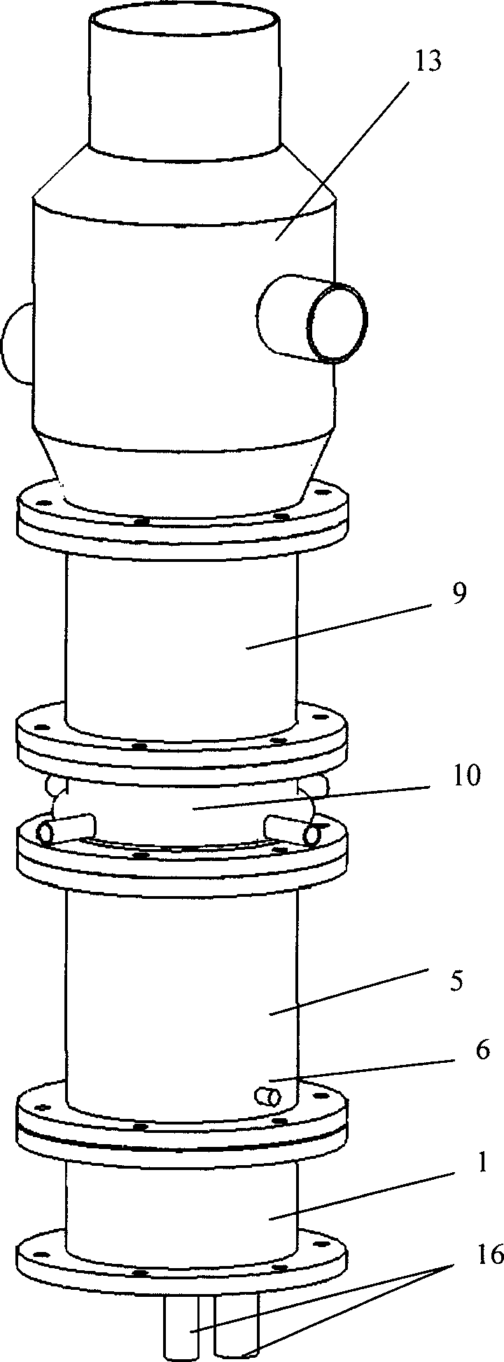
[0020] refer to figure 1 and figure 2 , The catalytic combustion furnace includes: gas premixing chamber 1, first catalytic combustion chamber 5, second catalytic combustion chamber 9, secondary gas or air mixing chamber 10, shell and tube heat exchanger 13 five main parts.

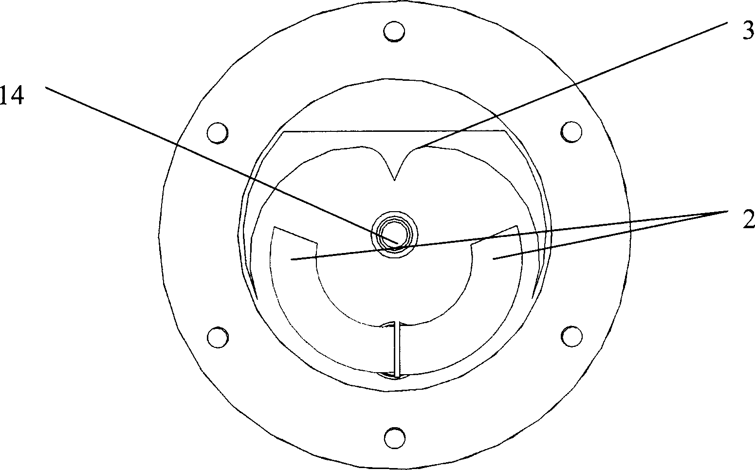
[0021] The air guide pipe 2 in the premixing chamber 1 is composed of two 1 / 4 arc circular tubes, the cyclone guide surface 3 is composed of four 1 / 4 arc cylindrical surfaces, and the center of the cyclone guide surface is The radius of the two 1 / 4 arcs is 1 / 5 of the radius of the two outer 1 / 4 arcs. Catalytic combustion chamber is made up of two catalytic combustion chambers of the first catalytic combustion chamber 5 and the second catalytic combustion chamber 9, the first catalytic combustion chamber 5 bottom is provided with igniter 6, and 2 layers of catalytic combus...


PUM

PropertyMeasurementUnit
Apertureaaaaaaaaaa
Cross-sectional areaaaaaaaaaaa

Abstract

The invention relates to a gas fuel catalyst burner, which can be used to heat system. Wherein, the pre-mixing room (1) has a air guide tube (2) and a cyclone guide surface (3) to mix the fuel gas and the air uniformly; the catalyst burning room is formed by two catalyst burning rooms as fuel-rich area and fuel-lack area; the second fuel or air mixing room (10) is arranged between two catalyst burning rooms, which comprises four tangential fuel gas or air nozzles (11) to form the cyclone to mix the secondary fuel gas and air and fuel gas uniformly; and a metallic porous plate (4) is between the pre-mixing room and the first catalyst burning room to avoid backfire. The invention can realize high efficiency and lower discharge.

Description

technical field [0001] The invention relates to a catalytic burner used for heating or heating (hot air) system, the fuel of which is natural gas, coal gas or liquefied petroleum gas, belonging to the field of energy utilization. Background technique [0002] Gas combustion methods include diffusion combustion and premixed combustion, both of which are flame combustion. Modern scientific research has proved that flame combustion has two fatal shortcomings: (1) Flame combustion is an oxidation reaction of burning substances with the participation of free radicals, which involves the gas phase initiation of free radicals (especially oxygen free radicals), which inevitably generates Part of the electronically excited state product releases energy in the form of visible light. This part of energy cannot be used and lost, resulting in low energy utilization. (2) The gas-phase initiation of free radicals causes nitrogen in the air to participate in the combustion reaction to for...

Claims


Application Information

Patent Timeline
IPC IPC(8): F23D14/18
Inventor 何洪戴洪兴訾学红
Owner BEIJING UNIV OF TECH
Why Eureka
Try Eureka