Method and system for dimming light sources

一种光源、可调节的技术,应用在光源的亮度领域

Inactive Publication Date: 2006-09-06
PATENT TREUHAND GESELLSCHAFT FUER ELECTRIC GLUEHLAMPEN M B H
View PDF4 Cites 29 Cited by
  • Summary
  • Abstract
  • Description
  • Claims
  • Application Information

AI Technical Summary

Problems solved by technology

Low PWM "on" times are also a serious problem for power stages powering LEDs, especially when the converter must cover variable input and output voltage ranges

Method used


Image

  • Method and system for dimming light sources
  • Method and system for dimming light sources
  • Method and system for dimming light sources

Examples


Embodiment Construction

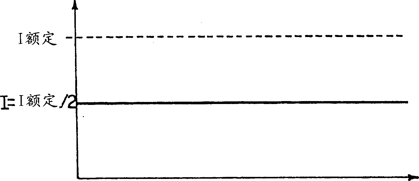
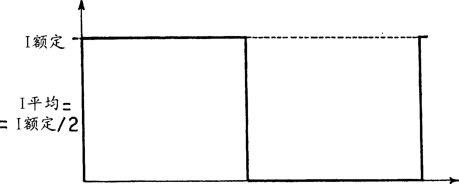
[0031] By direct comparison with reference figure 1 and 2 The CC and PWM devices described, the devices described here blend the two technologies while avoiding the disadvantages that each technology presents when used alone.

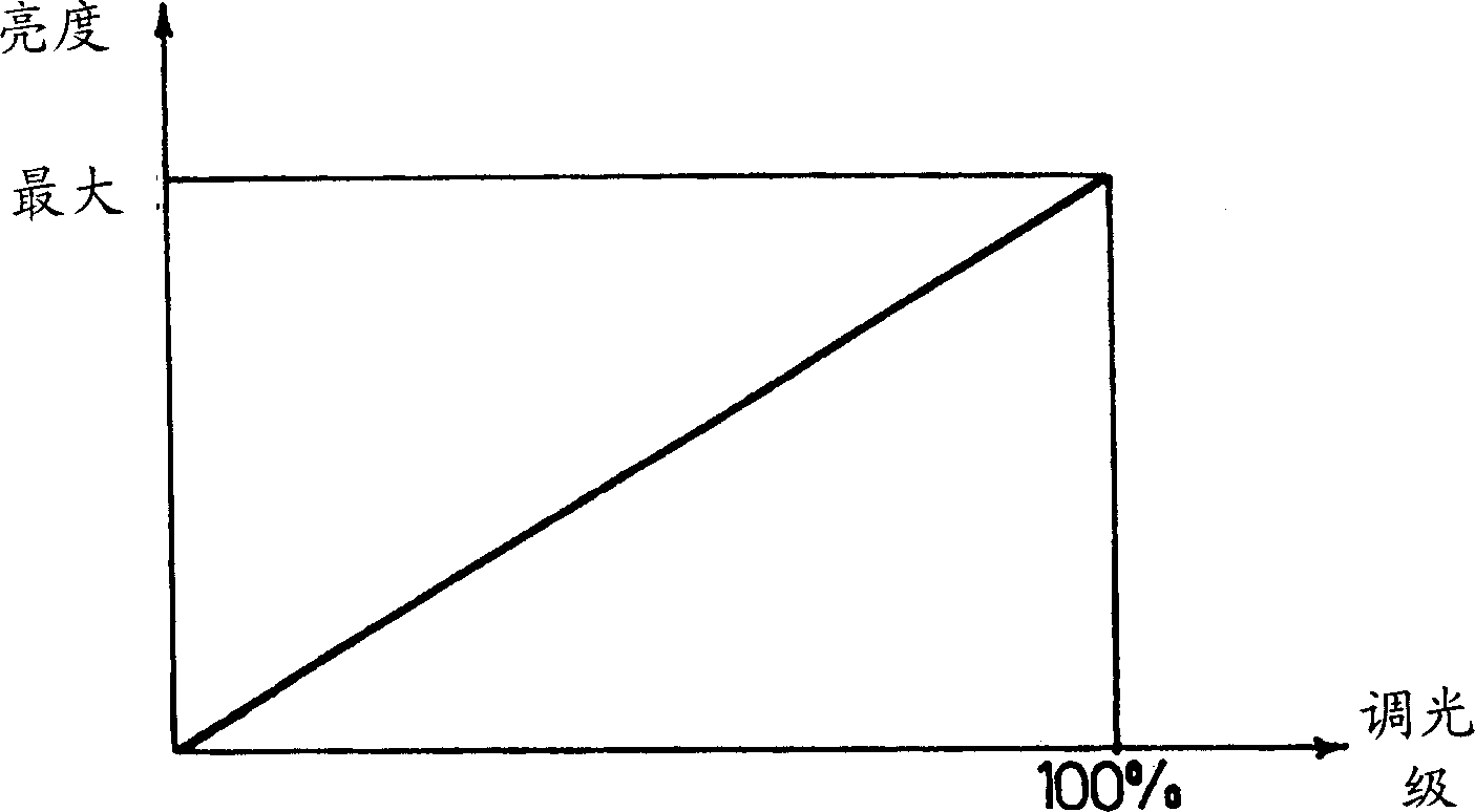
[0032] The purpose of the device described here is to realize the image 3 operation of the graph shown in the image 3 In , the abscissa scale (scale) represents the dimming level of the light source such as LED and the ordinate scale represents the brightness of the light source. Essentially, image 3 The graph of , corresponds to an exemplary linear relationship between dimming level (0-100%) and LED brightness (0-maximum). In accordance with standard practice in the industry, it is understood that the "dimming level" scale is indicated in terms of final light intensity, whereby 0% and 100% dimming levels correspond to no LED light and maximum light intensity, respectively.

[0033] As pointed out, image 3The linear relationship (ie function) ...


PUM


Abstract

Dimming a light source such as a LED over a dimming range (0%-100%) involves adjusting at least one of the intensity (I) and the duty-cycle (DR) of a current flowing through the light source. The dimming range includes at least one portion (L%-H%; 0%-H%) where the light source is fed with a current whose intensity (I) is switched with a given duty cycle (DR) between a non-zero on value and zero, the non-zero on value being a fraction of said rated value (Irated), whereby joint CC and PWM dimming is achieved.

Description

technical field [0001] The present invention relates to techniques for adjusting the brightness of light sources, such as light emitting diodes (LEDs). [0002] The invention has been designed with particular attention to possible applications in those devices in which the brightness of a light emitting diode is caused to vary as a function of the current flowing through the LED. Background technique [0003] Document DE-A-19810827 discloses a circuit for supplying current to a light-emitting diode (LED), wherein a current source is connected to the LED for supplying the current. The circuit includes logic gates to regulate the current supplied to the LEDs based on the LED temperature. This logic gate can reduce the current supplied to the LED when a temperature threshold is exceeded, and increase the current if the temperature falls below the threshold. The logic gate may provide a differential voltage of a flux voltage applied to the LED and a reference voltage with a co...

Claims


Application Information

Patent Timeline
Patent Type & Authority Applications(China)
IPC IPC(8): H05B33/08H05B44/00
CPCH05B41/3921H05B33/0848H05B45/14
Inventor P·德安娜
Owner PATENT TREUHAND GESELLSCHAFT FUER ELECTRIC GLUEHLAMPEN M B H
Why Eureka
Try Eureka