Scroll compressor

A scroll compressor and scroll technology, applied to rotary piston machinery, rotary piston pumps, mechanical equipment, etc., can solve problems such as performance degradation and increased lubricating oil

Inactive Publication Date: 2006-09-06
PANASONIC CORP
View PDF1 Cites 8 Cited by
  • Summary
  • Abstract
  • Description
  • Claims
  • Application Information

AI Technical Summary

Problems solved by technology

Therefore, the amount of lubricating oil entering the compression chamber increases, causing a further decrease in performance

Method used


Image

  • Scroll compressor
  • Scroll compressor
  • Scroll compressor

Examples


Embodiment Construction

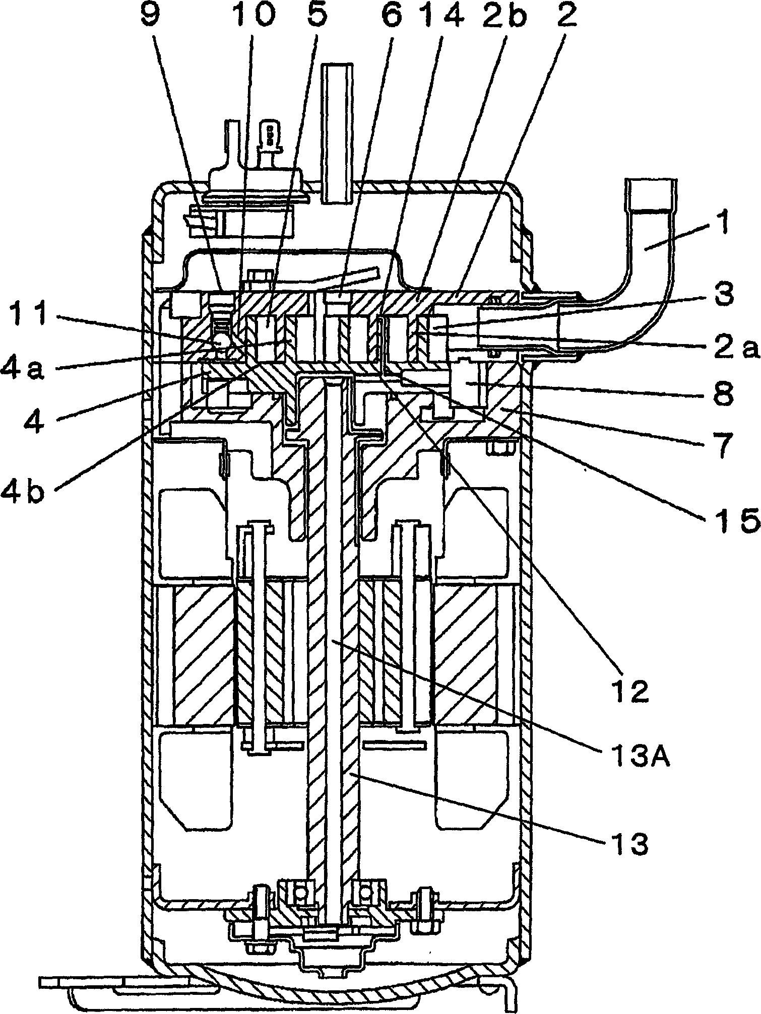
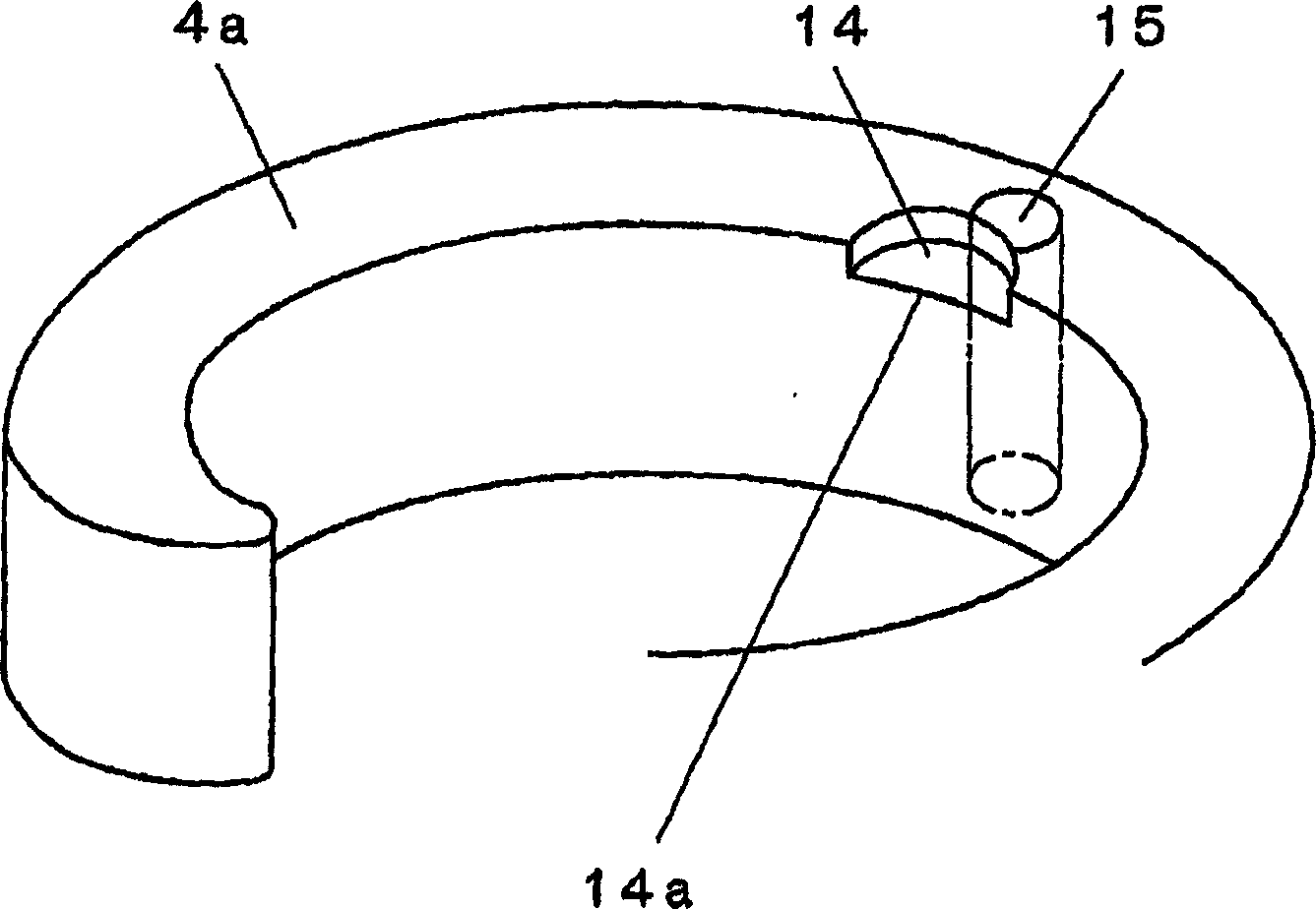
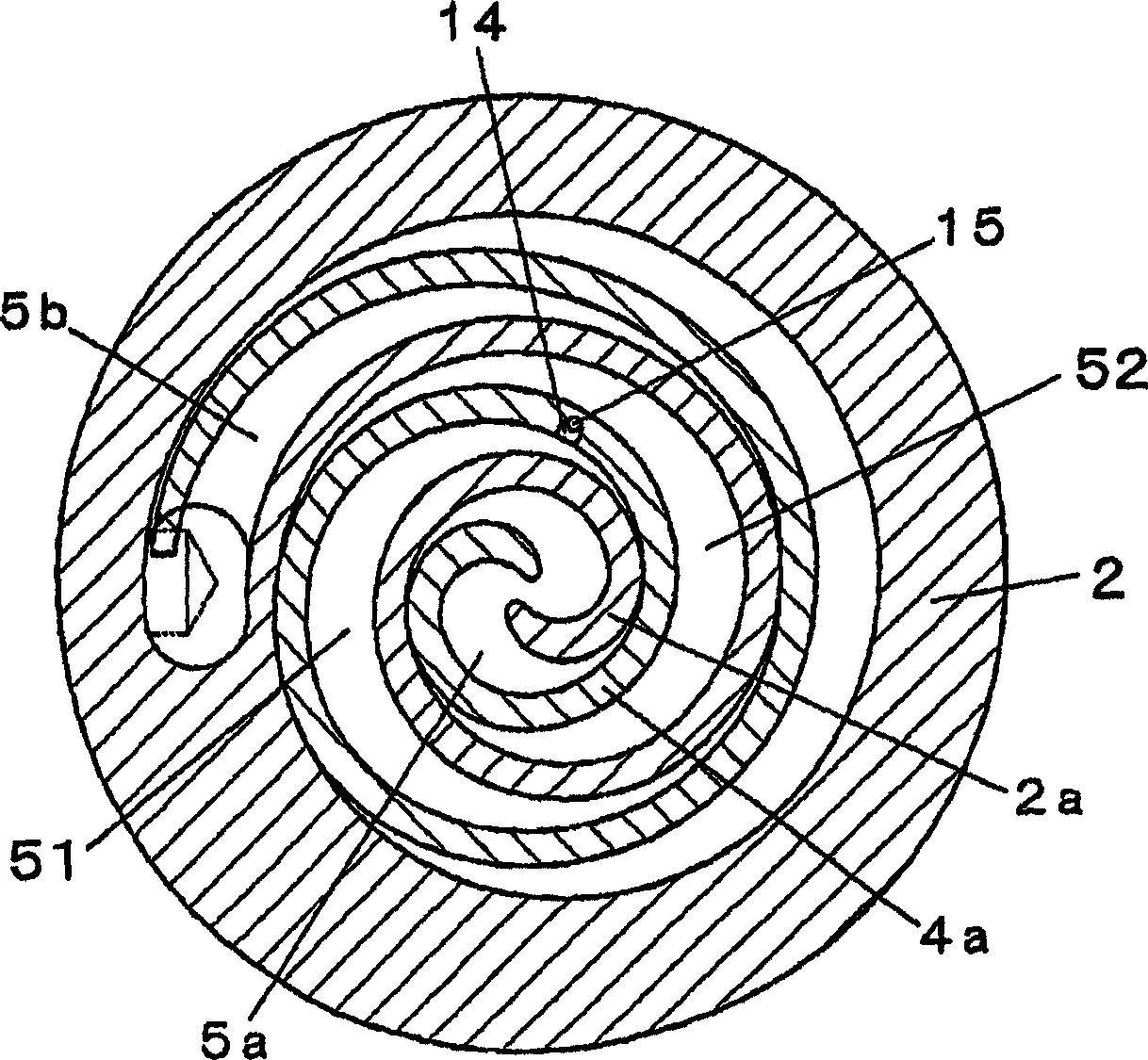
[0031] Figure 1-Figure 3 Indicates the first embodiment. In this figure, in order to clarify the difference between the scroll compressor of this embodiment and the conventional scroll compressor, Figure 7 Components that are identical or functionally equivalent are marked with the same symbols. Lubricating oil stored in the lower portion of the hermetic container passes through a passage 13A formed inside the shaft 13 , is depressurized by an orifice 12 mounted in the orbiting scroll 4 , and is supplied to the back pressure chamber 8 . In addition, a recessed portion 14 is provided at the front end of the wrap portion 4 a of the orbiting scroll member 4 , and a communicating passage 15 is provided that communicates between the recessed portion 14 and the rear surface of the mirror plate 4 b. In addition, in this embodiment, since the suction pipe 1 and the suction chamber 3 overlap with the back pressure adjustment mechanism 9, they are conveniently divided into left and r...


PUM


Abstract

In a scroll compressor, a stationary scroll part (2) and an orbiting scroll part (4) that have scroll wraps rising from end plates are engaged with each other to form a compression chamber (5) between the parts. The compressor performs suction, compression, and discharge when the compression chamber (5) moves while varying its volume, the movement occurring when the orbiting scroll part (4) orbits along a circular path while being restrained for rotation by a rotation restraining mechanism. A recess (14) is provided in an end face of a wrap (4a), on the opposite side of the end plate (4b). A connection path (15) for connecting the recess (14) and an end plate (4b) rear face is formed.

Description

technical field [0001] The present invention relates to a scroll compressor. In the scroll compressor, a fixed scroll member and an orbiting scroll member are meshed to form a compression chamber therebetween. The fixed scroll member and the orbiting scroll member are formed from The mirror plate erects the scroll body, and when the orbiting scroll member rotates in a circular orbit while the rotation is restricted by the rotation restriction mechanism, the compression chamber moves while changing the volume to perform suction, compression, and discharge. technical background [0002] As hermetic compressors for refrigeration and air conditioning, there are reciprocating, rotor, and scroll compressors, all of which are used in the field of refrigeration and air conditioning for home use and business use. Currently, developments are being made to make use of the respective characteristics in terms of cost, performance, and the like. [0003] Among them, compressors in which ...

Claims


Application Information

Patent Timeline
Patent Type & Authority Applications(China)
IPC IPC(8): F04C18/02F04C23/00
CPCF04C23/008F04C18/0292F04C18/0215
Inventor 鶸田晃二上义幸赤泽辉行饭田登泽井清
Owner PANASONIC CORP
Why Eureka
Try Eureka