Collecting device of spinning machine

A spinning machine and collection technology, applied in spinning machines, continuous winding spinning machines, textiles and papermaking, etc., can solve problems such as failure to combine fibers, clogging, and affecting collection effects

Inactive Publication Date: 2006-09-13
MASCHINENFABRIK RIETER AG
View PDF1 Cites 4 Cited by
  • Summary
  • Abstract
  • Description
  • Claims
  • Application Information

AI Technical Summary

Problems solved by technology

With known spinning machines of this type, the suction duct also has the disadvantage that there is no reinforcing plate between the two spinning spindles, the suction duct also extends directly to each front roller due to the extremely small thickness of the metal foil
The disadvantage is that, mainly, the fibers can be collected between each spinning position, but for some reason the fibers are not integrated into the fiber sliver when they are collected
These discrete individual fibers may at some point uncontrollably enter the fiber strip and / or become clogged in the perforations of the breathable conveyor belt, thereby gradually affecting the aggregation effect

Method used


Image

  • Collecting device of spinning machine
  • Collecting device of spinning machine

Examples


Embodiment Construction

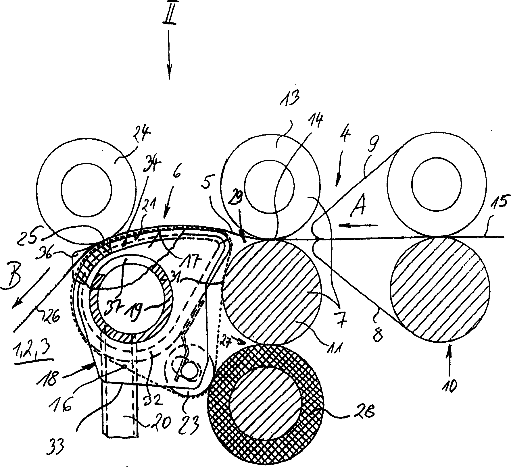
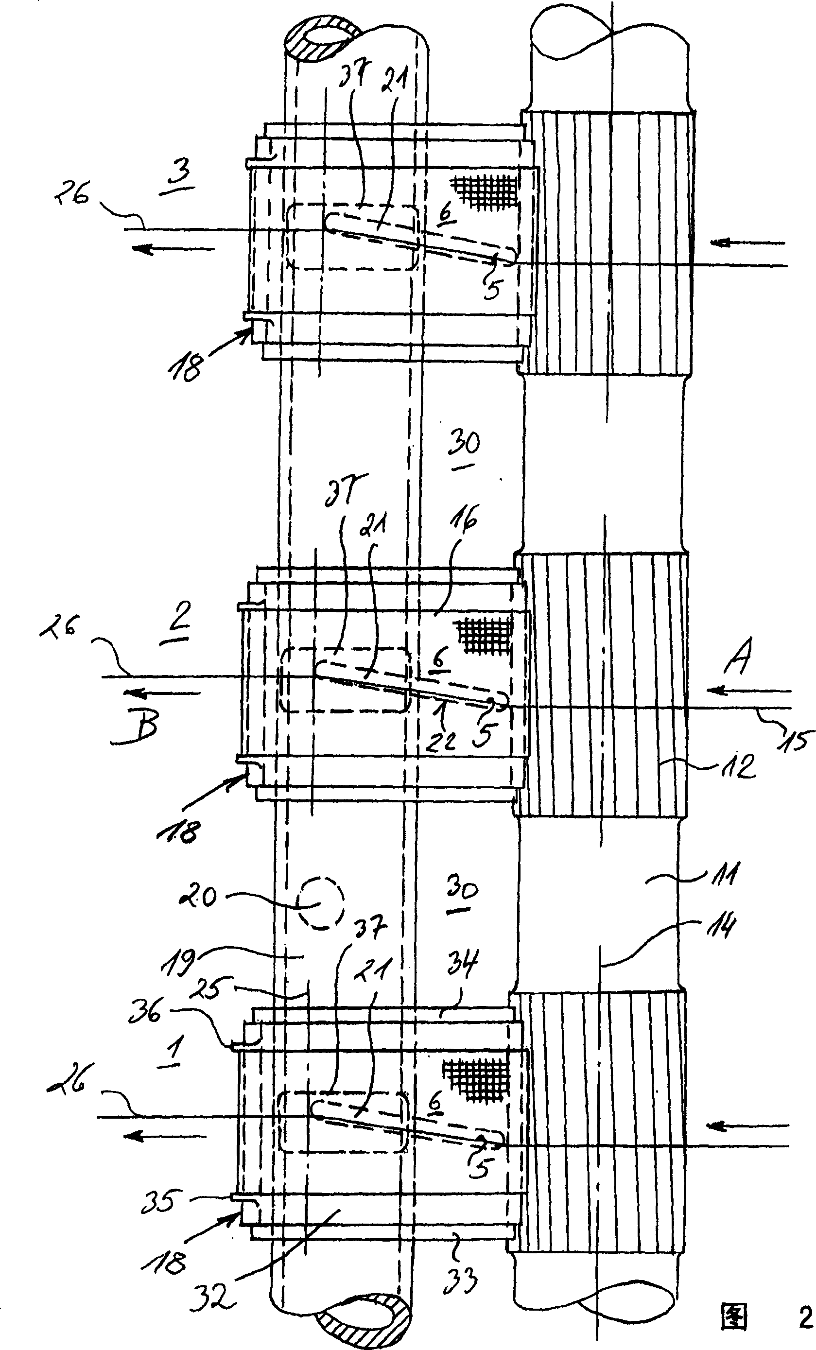
[0014] according to figure 1 The spinning machine shown in the part of Fig. 2 is firstly a ring spinning frame. Usually, this kind of spinning machine has many adjacently arranged spinning positions according to the longitudinal direction of the machine. From Fig. 2, it can be seen that three Spinning positions 1, 2 and 3.

[0015] Each spinning position 1, 2, 3... has a drafting unit 4, but in figure 1 Only its terminal area is drawn in the drawing, and there is a collection area 6 for bundling the drawn but untwisted fiber strip 5, which is located downstream of the drafting device 4. The other components of the spinning positions 1, 2, 3... are not shown.

[0016] Each drafting unit 4 has a pair of front rollers 7, and an apron roller 10 for guiding the lower apron 8 and the upper apron 9 mounted upstream of the pair of front rollers. All the other rollers of the drafting device 4 are not shown on the figure.

[0017] The front roller pair 7 has a driven bottom roller 1...


PUM


Abstract

The present invention relates to one spinning machine possessing many adjacent arranged spinning spindle sites. Each of the spinning spindle sites has one drafting device, one pair of front rollers to form the front nipper bite, and one collecting area below the drafting device to collect drafted fiber sliver. Each of the collecting areas contains one fiber sliver conveying air permeating conveying belt guided with one sliding plane possessing sucking slot. The sliding plane possessing sucking slot has separated cover set on the sucking pipe extending to many spindle sites. The sucking pipe is set in the place separated from the front roller pair by certain distance formed with the overlapped sliding planes of the covers.

Description

technical field [0001] The invention relates to a collection device for a spinning machine having a plurality of adjacently arranged spinning positions, each of which has a drafting device with a pair of front rollers, said The collection device is arranged downstream from the front roller of a spinning position to form a collection area, and the collection device also includes a guide surface with suction slots for slidingly supporting a An air-permeable conveyor belt for conveying the drafted fiber sliver leaving the front roller pair of the drafting device. Background technique [0002] The drawn fiber sliver in the drafting unit of the spinning machine is then given a spinning twist. If this spinning twist is applied directly after drafting, a so-called spinning triangle may form in the front roller pair of the drafting device, which triangle contains edge fibers that are not properly incorporated into the twisted yarn. In order to avoid this disadvantage, in recent ye...

Claims


Application Information

Patent Timeline
Patent Type & Authority Applications(China)
IPC IPC(8): D01H5/72D01H5/60D01H1/02D01H1/22D01H5/26D01H5/66D01H5/86D01H11/00
CPCD01H1/025D01H5/72D01H5/86D01H1/22D01H5/26
Inventor G·谢夫勒
Owner MASCHINENFABRIK RIETER AG
Why Eureka
Try Eureka