Acoustic signal processing apparatus and processing method thereof

A sound signal processing and sound signal technology, applied in the field of sound signal processing, can solve the problems that the sound source is limited, cannot handle various sounds, and the number of sound sources cannot be greater than the number of microphones, etc.

Inactive Publication Date: 2006-09-13
KK TOSHIBA
View PDF0 Cites 22 Cited by
  • Summary
  • Abstract
  • Description
  • Claims
  • Application Information

AI Technical Summary

Problems solved by technology

However, the estimation of the number and direction of sound sources and the estimation of the source sound are based on the harmonic structure, so the sound sources that can be processed are limited to those with harmonic structure, such as human voice
That is, the method cannot handle various sounds
[0005] As mentioned above, there are contradictory (self-contradictory) problems: (1) if the sound sources are not restricted, the number of sound sources cannot be greater than the number of microphones; and (2) if the number of sound sources is greater than the number of microphones, then These sources are limited to, for example, harmonic structures
That is, no method has been devised that can handle more sources than microphones without limiting those sources

Method used


Image

  • Acoustic signal processing apparatus and processing method thereof
  • Acoustic signal processing apparatus and processing method thereof
  • Acoustic signal processing apparatus and processing method thereof

Examples


Embodiment Construction

[0040] Embodiments of the sound signal processing apparatus according to the present invention will be described in detail below with reference to the accompanying drawings.

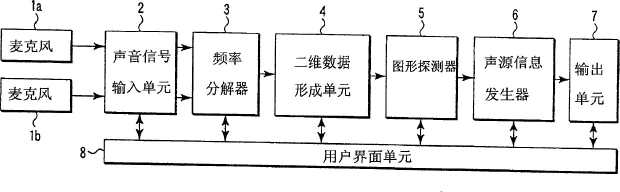
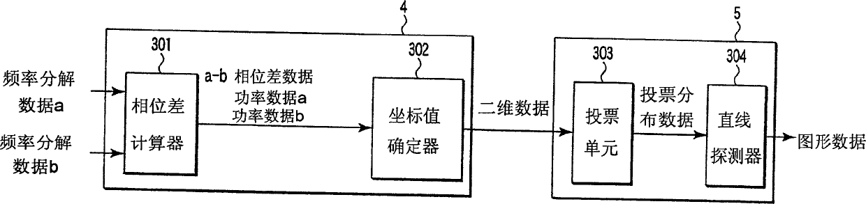
[0041] FIG. 1 is a functional block diagram of a sound signal processing device according to an embodiment of the present invention. The sound signal processing device includes: a microphone 1a, a microphone 1b, a sound signal input unit 2, a frequency resolver 3, a two-dimensional data forming unit 4, a pattern detector 5, a sound source information generator 6, an output unit 7 and a user interface unit 8.

[0042] [Basic principle of sound source estimation based on phase difference of each frequency component]

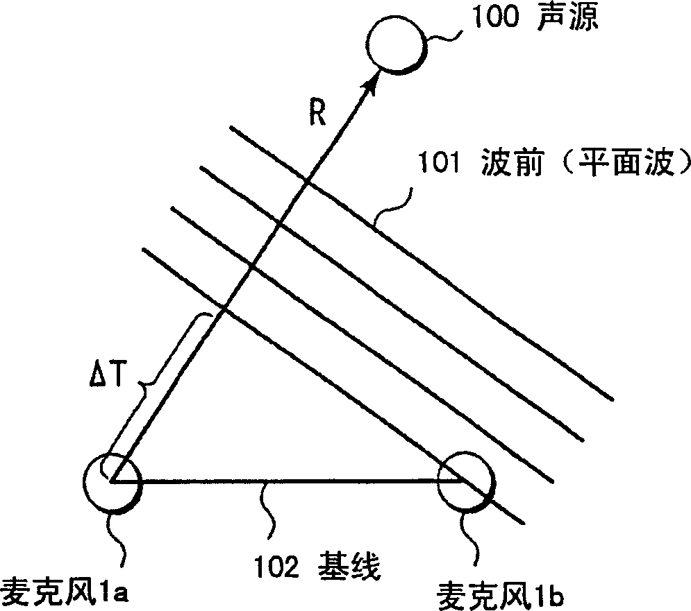
[0043] The microphones 1a and 1b are two microphones separated by a predetermined distance in a medium such as air. The microphones 1a and 1b are means for converting medium vibrations (sound waves) at two different points into electrical signals (sound signals). Microphones 1a and 1b are ...


PUM


Abstract

A frequency decomposer analyzes two amplitude data input from microphones to an acoustic signal input unit, and a two-dimensional data forming unit obtains a phase difference between the two amplitude data for each frequency. This phase difference for each frequency is given two-dimensional coordinate values to form two-dimensional data. A figure detector analyzes the generated two-dimensional data on an X-Y plane to detect a figure. A sound source information generator processes information of the detected figure to generate sound source information containing the number of sound sources as generation sources of acoustic signals, the spatial existing range of each sound source, the temporal existing period of a sound generated by each sound source, the components of each source sound, a separated sound of each sound source, and the symbolic contents of each source sound.

Description

technical field [0001] The present invention relates to sound signal processing and, in particular, to the estimation of the number of emission sources such as sound waves propagating in a medium, the direction of each emission source and the frequency content of the sound waves from each emission source. Background technique [0002] In recent years, in the field of robot hearing research, a method of estimating the number and direction of multiple target sound sources in a noisy environment (sound source localization) and separating and extracting each source sound (sound source separation) has been proposed. . [0003] For example, Futoshi Asano in "Separating Sounds" (Mesurement and Control, Vol.43, No.4, pp.325-330, April 2004) describes a method for Next, measure N sound sources through M microphones, generate a spatial correlation matrix from the data obtained by processing the output of each microphone using FFT (Fast Fourier Transform), decompose the matrix into ei...

Claims


Application Information

Patent Timeline
Patent Type & Authority Applications(China)
IPC IPC(8): G01S3/808G01S5/20G10L21/02G06F17/00G10L15/28G10L21/028
CPCG10L2021/02165H04R3/005G10L21/0272
Inventor 铃木薰古贺敏之
Owner KK TOSHIBA
Why Eureka
Try Eureka