Controlled impedance cable connector

A joint surface, ground plane technology, applied in the direction of conductive connection, connection, circuit, etc., can solve the problems of not easy to change to signal/ground structure, insufficient performance characteristics, increased time and cost, etc.

Inactive Publication Date: 2006-09-13
3M INNOVATIVE PROPERTIES CO
View PDF0 Cites 3 Cited by
  • Summary
  • Abstract
  • Description
  • Claims
  • Application Information

AI Technical Summary

Problems solved by technology

Such connectors are usually designed for a single type of application and are generally not easily adapted for e.g. different signal / ground structures, or for different types of connection methods such as soldering or soldering
Additionally, existing connectors are often difficult to assemble, often requiring multi-step molding processes, post-molding of electrical contacts, etc., which add time and expense to the connector manufacturing process
Finally, prior art joints often do not provide adequate performance characteristics for high performance systems
Inadequate performance characteristics include, for example, the inability to control the impedance within the connector, or to match the impedance of the connector to that of the system in which it is used

Method used


Image

  • Controlled impedance cable connector
  • Controlled impedance cable connector
  • Controlled impedance cable connector

Examples


Embodiment Construction

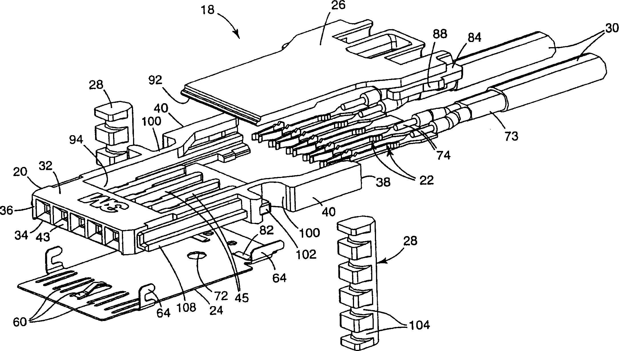
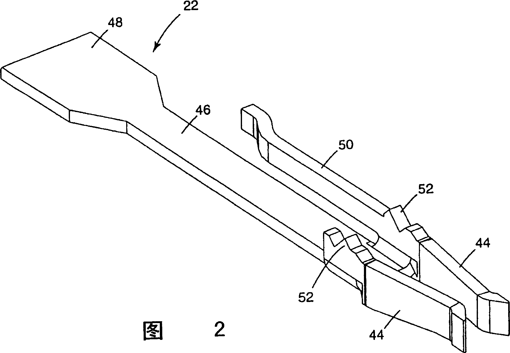
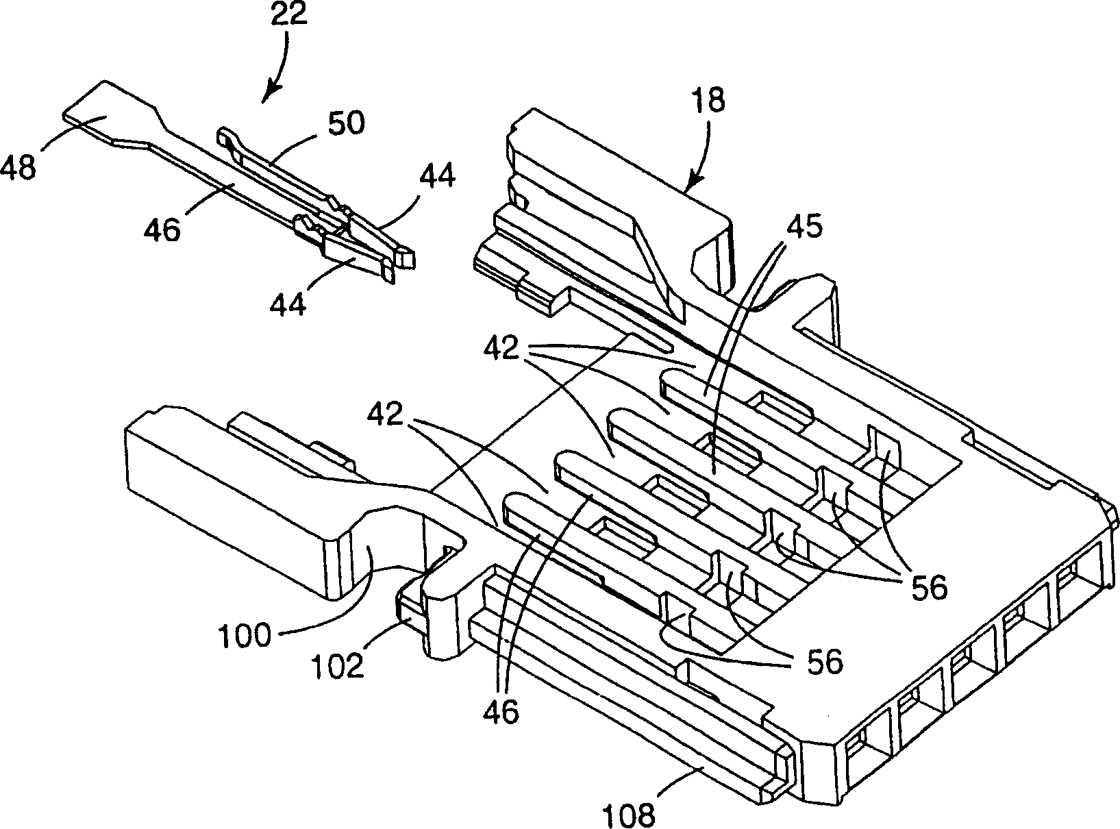
[0018] exist figure 1 The connector 18 of the present invention, shown in exploded view in FIG. 2 , includes a connector body 20 formed of a non-conductive insulating material, a plurality of receptacle contacts 22 , a flat conductive ground plate 24 and a cover member 26 . Retention bar 28 may be used when multiple joint bodies are stacked together. Connector 18 in figure 1 Indicated for use with a pair of twinax cables 30. However, as will be discussed in more detail below, the connector 18 of the present invention may be used with other types of shielded cables, such as coaxial or twisted pair cables.

[0019] The fitting body 20 includes a top side 32 and an opposite bottom side 34 . The top side 32 and the bottom side 34 are bounded by a leading edge 36 , a trailing edge 38 and two longitudinal side edges 40 . The top side 32 of the joint body 20 includes a plurality of channels 42 separated by ribs 45 extending from an opening 43 in the leading edge 36 toward the tra...


PUM


Abstract

An electrical connector for terminating a shielded cable and connecting the cable to regularly arranged contact pins. The connector includes a connector body formed from an insulative material. The connector body has an upper surface and an opposing lower surface defined by a front edge, a back edge and two longitudinal side edges. The upper surface includes a plurality of longitudinal channels adapted to receive a plurality of socket contacts. A planar conductive ground plate engages the bottom surface of the connector body and extends across each of the plurality of socket contacts to establish a ground plane across the entire connector. A cover member encloses the longitudinal channels and socket contacts. A plurality of individual connectors may be stacked together and retained in a stack by a removable retaining rod.

Description

[0001] This application is a divisional application of the patent application whose application number is 00815960.2 and the application date is February 1, 2000. technical field [0002] The present invention relates to a joint for coaxial, twinaxial and / or twisted pair cables. The invention is particularly applicable to the termination of shielded cables of the type described above so that a controlled impedance is provided through the connector from the mating face to the end of the cable. Background technique [0003] There are many types of connectors for terminating shielded cables. Such connectors are usually designed for a single type of application and are generally not easily adapted for eg different signal / ground configurations, or for different types of connection methods such as soldering or welding. Additionally, existing connectors are often difficult to assemble, often requiring multiple molding steps, post...

Claims


Application Information

Patent Timeline
Patent Type & Authority Applications(China)
IPC IPC(8): H01R9/05H01R9/24H01R13/502H01R13/514H01R13/646H01R13/658H05K5/00H01R13/6473H01R9/03H01R12/59H01R13/516H01R13/652H01R24/44
CPCH01R13/65802H01R9/2408H01R13/65807H01R12/592H01R2103/00H01R13/514H01R13/6592H01R9/035H01R13/6586H01R9/0512H01R13/502H01R24/44H01R13/6582H01R13/65915H01R13/6473
Inventor S·费尔德曼W·C·乔R·J·谢雷尔
Owner 3M INNOVATIVE PROPERTIES CO
Why Eureka
Try Eureka