Braking device and electric tool contg. the same

A technology of brake device and brake disc, applied in the combination of coupling and brake, mechanical equipment, etc., can solve the problems of high precision requirements and slippage of parts, and achieve the effect of small braking impact force, safe operation, simple and reliable structure

Active Publication Date: 2006-09-20
SUZHOU KINGCLEAN PRECISION MACHINERY
View PDF0 Cites 7 Cited by
  • Summary
  • Abstract
  • Description
  • Claims
  • Application Information

AI Technical Summary

Problems solved by technology

[0002] In order to make the blade of the electric tool similar to the green pole machine stop quickly when the power tool is stopped, the previous torsion spring clutch brake structure is to fit the torsion spring in the hole of the large gear and the eccentric block seat by interference, and through the reverse direction of the torsion spring Tension force transmission, when braking, tighten one end of the torsion spring through the cage to make the blade and the motor clutch. The disadvantage is that the precision of the parts is high, and it is easy to cause slippage when transmitting a large torque.

Method used


Image

  • Braking device and electric tool contg. the same
  • Braking device and electric tool contg. the same
  • Braking device and electric tool contg. the same

Examples


Embodiment

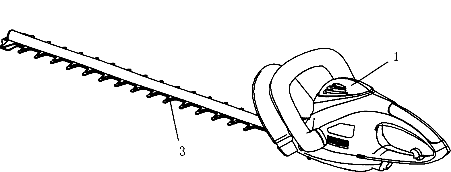
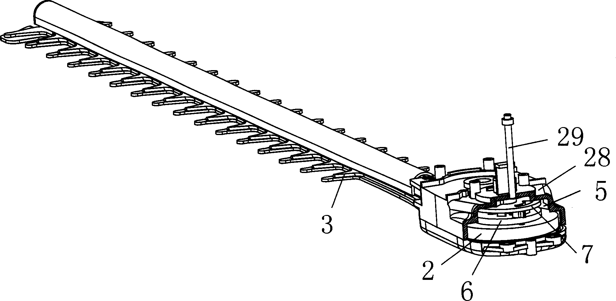
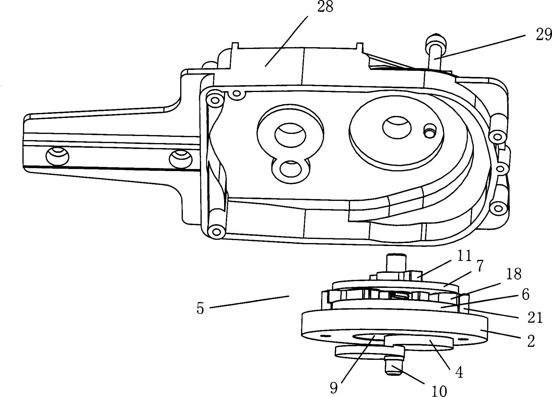
[0022] Example: such as figure 1 , figure 2 , image 3 , Figure 4 , Figure 5 As shown, a braking device and an electric tool containing the braking device include a large gear 2 driven by a driving device 1, the large gear 2 drives the eccentric block 4 through the clutch device 5, the eccentric block 4 drives the blade 3 to work, and the clutch device 5 It includes the eccentric block 4 located below the large gear 2, the brake disc 6 located above the large gear 2 and the holding disc 7 above the brake disc 6, the center of the large gear 2 is provided with a rotating hole 8, and the upper part of the eccentric block 4 is fixed with a rotating disc 9 , the rotating hole 8 is set outside the rotating disk 9, and the rotating shaft 10 is fixed on the rotating disk 9, and the rotating shaft 10 passes through the brake disc 6 and the holding disc 7 in turn upwards, and the rotating disc 9 and the braking disc 6 are connected and fixed by the connecting pin 25, and the rota...


PUM


Abstract

The present invention discloses a brake device and electric tool containing said brake device. Said brake device includes the following several portions: large gear which is driven by a drive device; eccentric block which is driven by large gear through the agency of a clutch device, said eccentric block can be used for driving tool blade and making it work, the described clutch device includes a brake disk positioned over said large gear, the eccentric block is positioned under the large gear, and coaxially-connected and fixed with said brake disk, and a pair of shifting forks is pin-connected on the brake disk. Besides, said invention also provides the concrete working principle of said brake device and its concrete operation method.

Description

technical field [0001] The invention relates to a brake device and an electric tool containing the brake device. Background technique [0002] In order to make the blade of the electric tool similar to the green pole machine stop quickly when the power tool is stopped, the previous torsion spring clutch brake structure is to fit the torsion spring in the hole of the large gear and the eccentric block seat by interference, and through the reverse direction of the torsion spring Tension force transmission, when braking, tighten one end of the torsion spring through the cage to make the blade and the motor clutch. The disadvantage is that the precision of the parts is high, and it is easy to cause slippage when transmitting a large torque. Contents of the invention [0003] The object of the present invention is to provide a brake device and an electric tool containing the brake device, which can disengage the blade from the driving device and stop immediately when the device...

Claims


Application Information

Patent Timeline
Patent Type & Authority Applications(China)
IPC IPC(8): F16D67/02
Inventor 倪祖根
Owner SUZHOU KINGCLEAN PRECISION MACHINERY
Why Eureka
Try Eureka