Check patentability & draft patents in minutes with Patsnap Eureka AI!

Net like heat pipe and its mfg. method

A manufacturing method and mesh technology, applied in indirect heat exchangers, lighting and heating equipment, etc., can solve the problems of inconvenient bending or flattening of heat pipes.

Inactive Publication Date: 2006-09-20
FU ZHUN PRECISION IND SHENZHEN +1
View PDF0 Cites 4 Cited by
  • Summary
  • Abstract
  • Description
  • Claims
  • Application Information

AI Technical Summary

Problems solved by technology

[0005] In order to solve the above-mentioned problem of inconvenient bending or flattening of heat pipes, an example of a mesh heat pipe that is easy to bend or flatten and a manufacturing method of the mesh heat pipe are described here

Method used


Image

  • Net like heat pipe and its mfg. method
  • Net like heat pipe and its mfg. method
  • Net like heat pipe and its mfg. method

Examples


Embodiment Construction

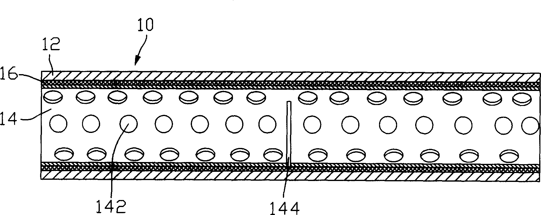
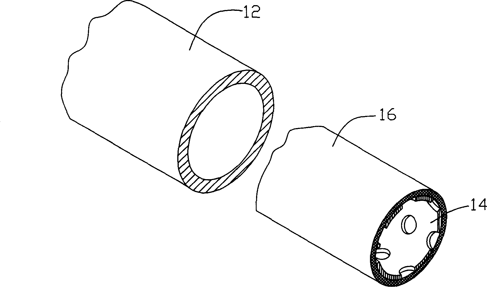
[0017] figure 1 It is a schematic axial cross-sectional view of the first embodiment of the mesh heat pipe of the present invention. The heat pipe 10 includes an outer pipe 12, an inner pipe 14, and a mesh capillary structure layer sandwiched between the outer pipe 12 and the inner pipe 14. 16. Wherein, the outer tube 12 is made of a metal with good thermal conductivity, such as copper, and the inner tube 14 provides a balanced external tension pressure on the capillary structure layer 16 arranged on the inner wall of the outer tube 12, so that the capillary structure layer 16 is integrally tight. It is pasted on the inner wall of the outer tube 12 so as to provide a good and effective heat transfer channel between the outer tube 12 and the working liquid (not shown) in the tube. The surface of the inner tube 14 is provided with a plurality of circular holes 142 through which the working liquid filled in the tube can pass through the holes 142 and communicate with the capilla...


PUM


Abstract

The present invention discloses a mesh screen type heat pipe and its manufacture method. Said mesh screen type heat pipe includes external pipe, internal pipe and mesh screen type capillary structure layer sandwiched between external pipe and internal pipe, said internal pipe can be used for supporting the described capillary structure layer and making it be tightly close to the external pipe. On said internal pipe several notches are set, and said mesh screen type heat pipe is made up by heating external pipe and inserting the internal pipe covered with said mesh screen type capillary structure layer into said external pipe. Besides, said invention also provides the concrete application method and application field of said mesh screen type heat pipe.

Description

【Technical field】 [0001] The invention relates to the field of heat dissipation, in particular to a mesh-type heat pipe for heat transfer using the principle of phase change and a manufacturing method thereof. 【Background technique】 [0002] In the existing field of heat dissipation, heat pipes are widely used due to their fast heat transfer characteristics. They use the principle that the working liquid in the shell absorbs or releases a large amount of heat when the gas and liquid phases are transformed. The inner wall of the shell is usually A capillary structure (Capillary Wick Structure) is provided to facilitate the reflux of the condensed liquid. The function of the capillary structure is mainly to provide the driving force required for the rapid reflux of the condensed liquid on the one hand, and on the other hand to provide the interface between the inner wall of the shell and the liquid-gas interface in the shell. heat conduction path. At present, the commonly use...

Claims


Application Information

Patent Timeline
Patent Type & Authority Applications(China)
IPC IPC(8): F28D15/04
CPCF28D15/046
Inventor 洪居万骆长定吴荣源郑景太
Owner FU ZHUN PRECISION IND SHENZHEN
Features
  • R&D
  • Intellectual Property
  • Life Sciences
  • Materials
  • Tech Scout
  • Unparalleled Data Quality
  • Higher Quality Content
  • 60% Fewer Hallucinations
Learn More