Handling large, heavy workpieces using gantry robots with two robot arms

A robotic arm and gantry technology, applied in the system field of remote control machinery, can solve the problems of complicated installation, reduced load, long debugging time, etc., and achieve the effect of saving workshop floor space, simplifying tools, and improving process flow.

Inactive Publication Date: 2006-09-27
FANUC ROBOTICS NORTH AMERICA
View PDF0 Cites 11 Cited by
  • Summary
  • Abstract
  • Description
  • Claims
  • Application Information

AI Technical Summary

Problems solved by technology

Such devices are stereotyped, or require highly complex structures to obtain the required adaptability
They take up a lot of space, are complex to install and require long commissioning times, especially when they are large enough to accommodate particularly large workpieces
[0007] The traditional crane frame is not easy to support workpiece steering and workpiece conveying control. It generally requires large tools to hold large workpieces. The design of tools is very complicated, especially when workpiece steering is required and the steering function is integrated into the tool.
Traditional crane racks require very high top beam spacing if fixed vertical columns are used, or are costly and load dropping if telescoping vertical columns are used

Method used


Image

  • Handling large, heavy workpieces using gantry robots with two robot arms
  • Handling large, heavy workpieces using gantry robots with two robot arms
  • Handling large, heavy workpieces using gantry robots with two robot arms

Examples


Embodiment Construction

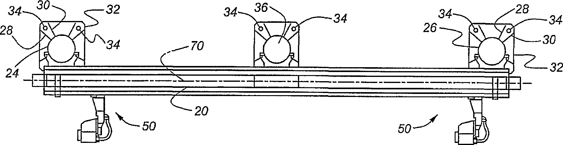
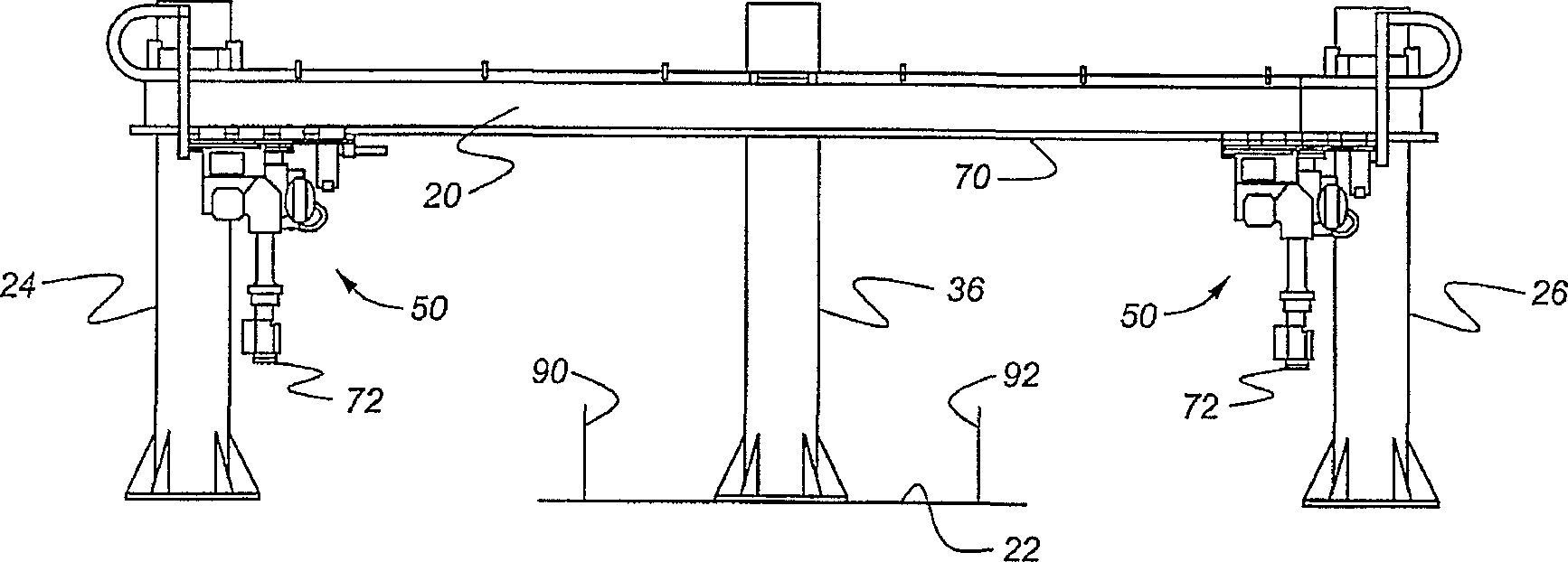
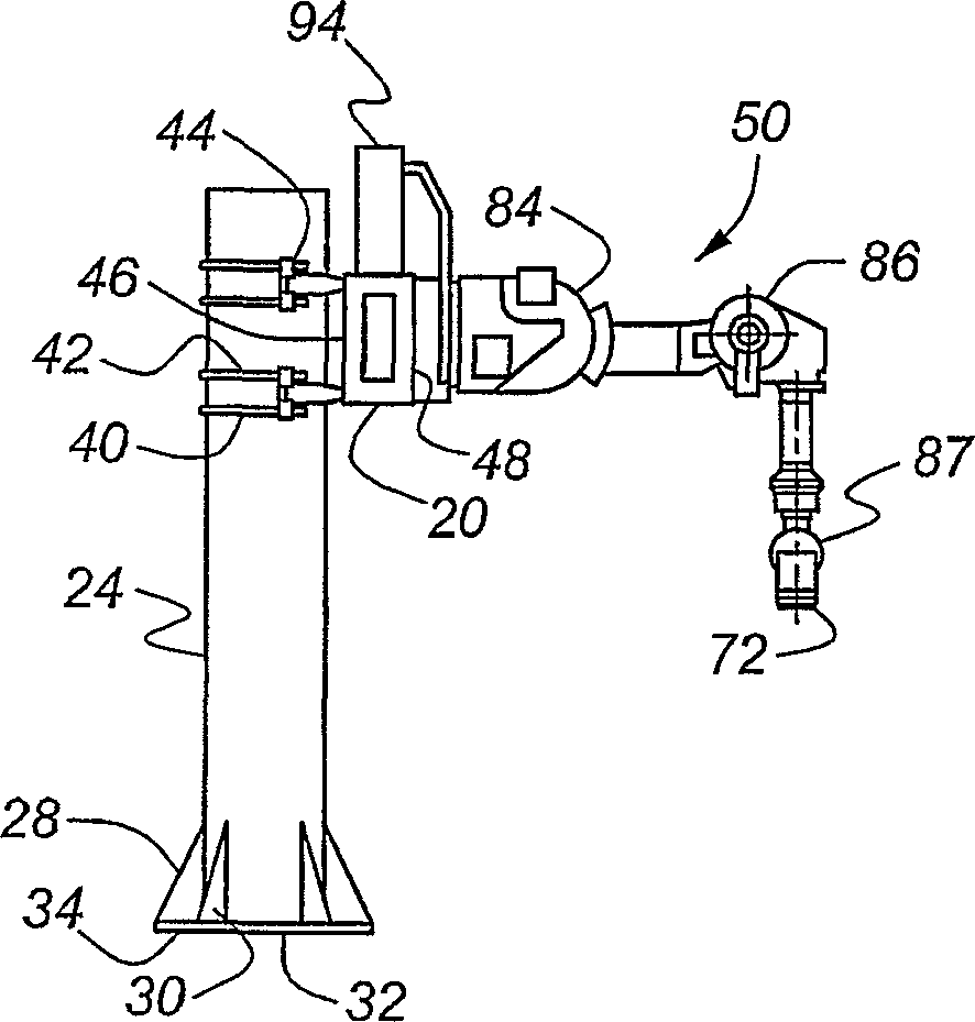
[0022] Figure 1-4 A guide rail 20 suspended above a factory floor 22 work area is depicted. The rail 20 is supported near both ends by posts 24, 26, preferably in the shape of hollow cylindrical tubes. A pair of flanges 28, 30 are located at the bottom of each column, extending radially from the column, and the flanges are welded to the column and the chassis 32 together. Screws 34 located around the periphery of the chassis 32 secure the chassis 32 to the floor 22, or to a support surface at or near the level of the floor. When the span between the columns 24 , 26 exceeds a preset length, at least one additional column 36 can be added between the columns 24 , 26 at both ends to provide intermediate support for the guide rail 20 .

[0023] image 3 and 4 The guide rail 20 is depicted affixed to the columns 24, 26 with a short distance apart by pairs of U-shaped bolts 40, 42 which tighten the circular profile of the columns and are secured by anchors 44 threaded over the b...


PUM


Abstract

A robot system for handling and transporting workpieces in a workspace includes a rail (20) supported above a floor, at least two robot arms (50) supported on the rail for mutual relative displacement and coordinated displacement along the rail, each arm articulating about multiple axes for engaging and supporting the workpiece (76), and a controller (96) communicating with each of the robot arms to control displacement and articulation of each robot arm, whereby the workpiece is engaged by each gripper (78, 80), lifted above the floor on the robot arm, carried along the rail, and released from the gripper at its destination.

Description

[0001] References relevant to this application [0002] This patent application claims subject matter of US Provisional Patent Application No. 60 / 488,668, filed July 18, 2003, the entire contents of which are hereby incorporated by reference. technical field [0003] The present invention relates to material handling of workpieces using coordinated gantry, and in particular, the present invention relates to a system comprising a plurality of remotely operated robots (robots) movable along guide rails. Background technique [0004] Purpose-built automatic transfer equipment, heavy-duty area crane gantry and heavy-duty pedestal remote-controlled machinery are all conventional techniques used to transfer large and heavy workpieces over short distances on the shop floor as required. [0005] A single heavy-duty remote-controlled machine usually requires a large tool to grasp a large workpiece, which seriously affects the payload available for the workpiece, and the design of suc...

Claims


Application Information

Patent Timeline
Patent Type & Authority Applications(China)
IPC IPC(8): B25J9/02B25J9/00B25J9/04B25J9/16
CPCB25J9/046B25J9/1682G05B2219/39124G05B2219/40293B25J9/0084B25J9/026
Inventor 尼尚特·雅韦里兰加纳特·米斯拉伊恩·奥尔理查德·M·莫特利
Owner FANUC ROBOTICS NORTH AMERICA
Why Eureka
Try Eureka