Winding device

A technology of winding and supporting devices, which is applied in the directions of transportation and packaging, conveying filamentous materials, and thin material processing, etc., which can solve the problems of high winding frequency and impossibility to compensate yarn tension fluctuations, etc., so as to improve quality and structure reliable effect

Active Publication Date: 2006-09-27
STARLINGER & CO GMBH
View PDF0 Cites 8 Cited by
  • Summary
  • Abstract
  • Description
  • Claims
  • Application Information

AI Technical Summary

Problems solved by technology

However, it is difficult to satisfy this criterion in a satisfactory manner according to the known winding devices
Especially with high winding frequencies, it is not possible to compensate for yarn tension fluctuations between the bobbin edge and the bobbin center by using a motor control system

Method used


Image

  • Winding device
  • Winding device
  • Winding device

Examples


Embodiment Construction

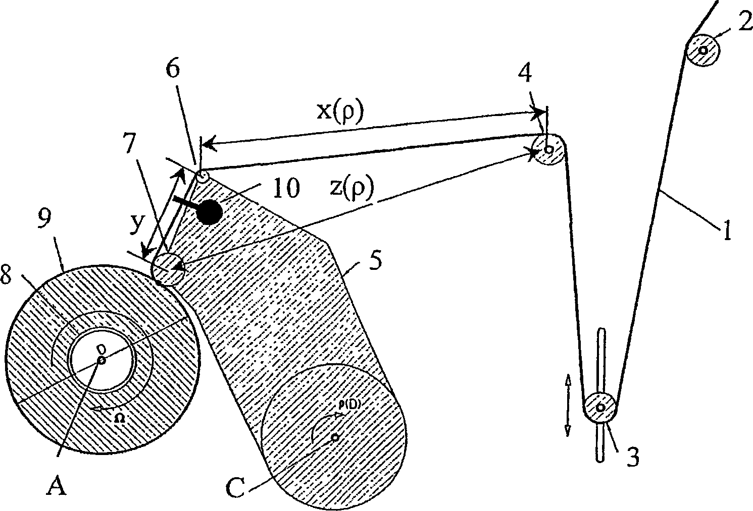
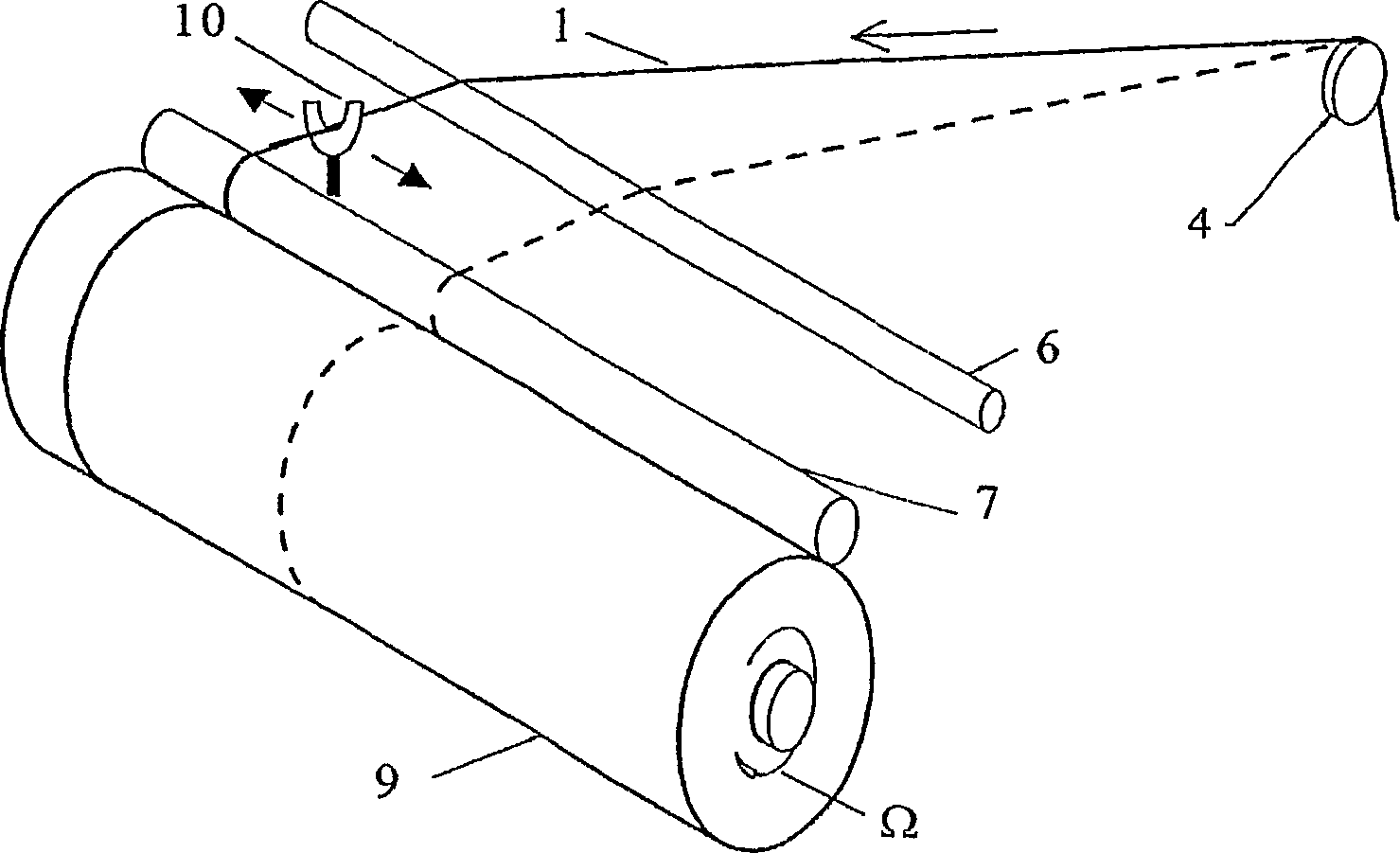
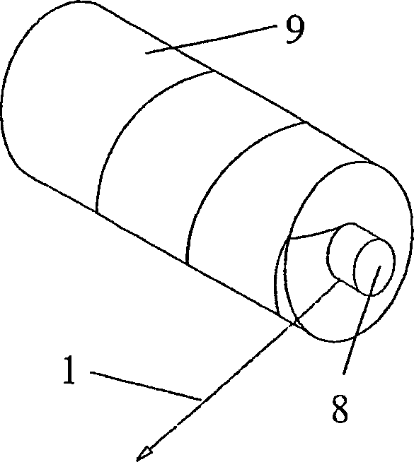
[0037] In FIG. 4A there is a first embodiment of the winding device according to the invention, which is an improvement of the known winding device according to FIG. 1 . During production, the yarn 1 or ribbon reaches the first turning guide roller 2 of the winding device. From there, the yarn 1 advances towards a yarn tension sensor 13 fitted with deflecting guide rollers. Embodiments of the yarn sensor 13 will be described in detail below. The yarn 1 advances from the yarn tension sensor 13 to a yarn support device 14 which may be a deflecting guide roller rotatably mounted on a support 15a of the control device 15 . The control device 15 additionally comprises a yarn deflecting device 6, for example, in this embodiment, a straight diverting bow, and also a pressure roller 7, which first presses the yarn 1 against the The surface of the core 8 is then pressed against the periphery of the forming bobbin 9 as the bobbin 9 is formed from the supplied yarn. The cartridge core...


PUM


Abstract

A bobbin winding device for generating a bobbin by winding a thread or bandlet onto a bobbin core comprises fixing means ( 12 ) for holding a bobbin core ( 8 ) and rotating it around an axis of rotation (A), thread-pressing means ( 7 ) for pressing a thread ( 1 ) or bandlet against the peripheral surface of a bobbin ( 9 ) that builds up on the bobbin core ( 8 ), whereby the thread-pressing means are movable essentially radially relative to the axis of rotation (A), a traversing thread guide ( 10 ) located close to the thread-pressing means ( 7 ) for reciprocating the thread ( 1 ) or bandlet along the axis of rotation (A), and thread-support means ( 14 ) for conducting the thread supplied to the bobbin or bobbin core, respectively, in an axially stationary manner relative to the axis of rotation (A). The thread-pressing means ( 7 ) are movable essentially radially relative to the axis of rotation (A) together with the thread-support means ( 14 ) so that the distance (z) between the thread-pressing means ( 7 ) and the thread-support means ( 14 ) will remain constant.

Description

technical field [0001] The invention relates to a winding device for winding yarn or ribbon onto bobbin cores according to the preamble of claim 1 . Background technique [0002] The winding device winds the yarn or ribbon onto a bobbin core, usually having a cylindrical or conical shape, to form a bobbin. In the schematic side view of the known winding device shown in Fig. 1, during production, the yarn 1 reaches the first turning guide roller 2 of the winding device. From there, the yarn proceeds to a "tensioner roller 3", which is a spring-loaded deflectable diverting guide roller, on which the yarn is diverted and tensioned. The yarn advances from a tensioning roller 3 to another deflection guide roller 4 and from 4 to a control device 5 . The control device includes a yarn deflection device 6 that can be made into a turning arc structure and a pressing roller 7, which first presses the yarn on the circumferential surface of the bobbin core 8 at the beginning of the wi...

Claims


Application Information

Patent Timeline
Patent Type & Authority Applications(China)
IPC IPC(8): B65H54/36B65H59/00
CPCB65H59/005B65H2701/31B65H54/36
Inventor 彼得·施马尔霍东斯
Owner STARLINGER & CO GMBH
Why Eureka
Try Eureka