
Seal mechanism for fluid machine

A technology of fluid machinery and sealing mechanism, which is applied in the field of centrifugal pump, fluid machinery sealing mechanism and fluid machinery, and can solve problems such as noise

Active Publication Date: 2006-09-27
EBARA CORP
View PDF0 Cites 2 Cited by
  • Summary
  • Abstract
  • Description
  • Claims
  • Application Information

AI Technical Summary

Problems solved by technology

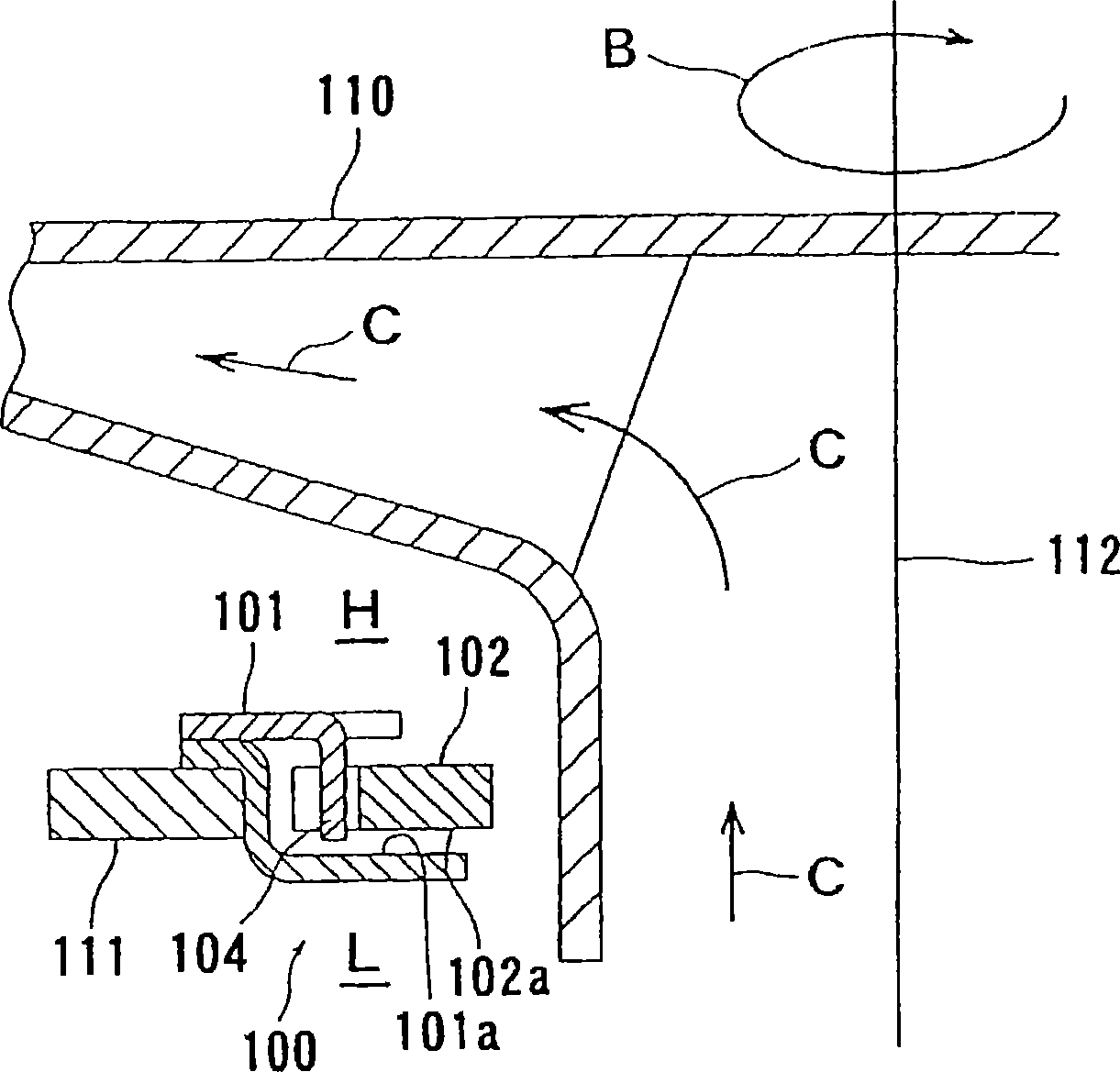
Therefore, if the back ring 102 moves together with the impeller 110, the back ring 102 will hit the curved portion 104, thereby generating noise

Method used


Image

  • Seal mechanism for fluid machine
  • Seal mechanism for fluid machine
  • Seal mechanism for fluid machine

Examples


Embodiment Construction

[0037] The following will refer to Figure 4 to Figure 17 A sealing mechanism for a fluid machine according to an embodiment of the present invention will be described. In the drawings, the same or corresponding components are denoted by the same or corresponding reference numerals, and description will not be repeated hereafter.

[0038] Figure 4 to Figure 6 The arrangement of the sealing mechanism 10 according to the first embodiment of the present invention is shown. Figure 4 is a top view of the sealing mechanism 10, Figure 5 is along Figure 4 A cross-sectional view obtained at the midline V-V, and Figure 6 is a cross-sectional view showing the sealing mechanism 10 and the impeller 13 of the centrifugal pump. Such as Figure 5 As shown in , the sealing mechanism 10 includes a housing (hood) 11 and an annular back ring (seal) 12 accommodated in the housing 11 .

[0039] The housing 11 includes an upper plate 11a provided on the high-pressure space H side and a l...


PUM


Abstract

A seal mechanism ( 10 ) can reduce noise during operation. The seal mechanism ( 10 ) is used for a fluid machine (P) to prevent a fluid from leaking out of a high-pressure space (H) into a low-pressure space (L) in the fluid machine (P). The seal mechanism ( 10 ) has an annular seal member ( 12 ) movable in a radial direction and a housing ( 11 ) disposed between a body ( 23 ) of the fluid machine (P) and a rotatable member ( 22 ) located inside the body ( 23 ) of the fluid machine (P) so as to receive the annular seal member ( 12 ). The annular seal member ( 12 ) has a first surface ( 12 a) on a side of the low-pressure space (L) in the fluid machine (P). The housing ( 11 ) has a second surface ( 11 c) facing the first surface ( 12 a) of the annular seal member ( 12 ). The seal mechanism ( 10 ) has one or more passages ( 15 ) formed in the first surface ( 12 a) and / or the second surface ( 11 c).

Description

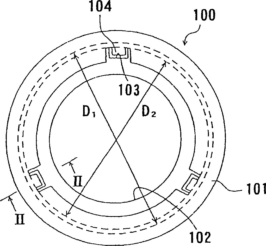
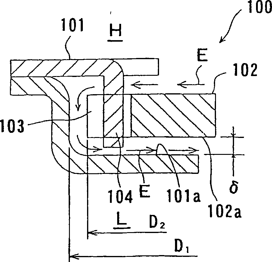
technical field [0001] The present invention relates to a sealing mechanism of a fluid machine; more particularly, to a sealing mechanism for preventing fluid from leaking from a high-pressure space into a low-pressure space between a body and a rotating part of a fluid machine. The present invention also relates to a fluid machine having such a sealing mechanism; more particularly, to a centrifugal pump having such a sealing mechanism. Background technique [0002] Typically, a fluid machine has a sealing mechanism for preventing fluid from leaking from a high-pressure space into a low-pressure space. For example, a centrifugal pump representing a fluid machine has a sealing mechanism for sealing liquid at a mouth ring of an impeller and a portion where a main shaft or a bushing passes through the body of the centrifugal pump. Figure 1 to Figure 3 The arrangement of a conventional sealing mechanism is shown. figure 1 is a top view of a conventional sealing mechanism 100,...

Claims


Application Information

Patent Timeline
IPC IPC(8): F16J15/44F04D29/16F04D29/08F04D29/42F16J15/40
CPCF04D29/167F16J15/406F16J15/441
Inventor 伊藤昭二川畑润也
Owner EBARA CORP
Learn More