Information display system, information processing device, indication device and mark display method
A technology of information processing device and information display device, which is applied in electrical digital data processing, input/output process of data processing, instruments, etc., and can solve the problems of not considering the indicated position, the problem of beam safety, inputting any command, etc.
- Summary
- Abstract
- Description
- Claims
- Application Information
AI Technical Summary
Problems solved by technology
Method used
Image

Examples
Embodiment approach 1
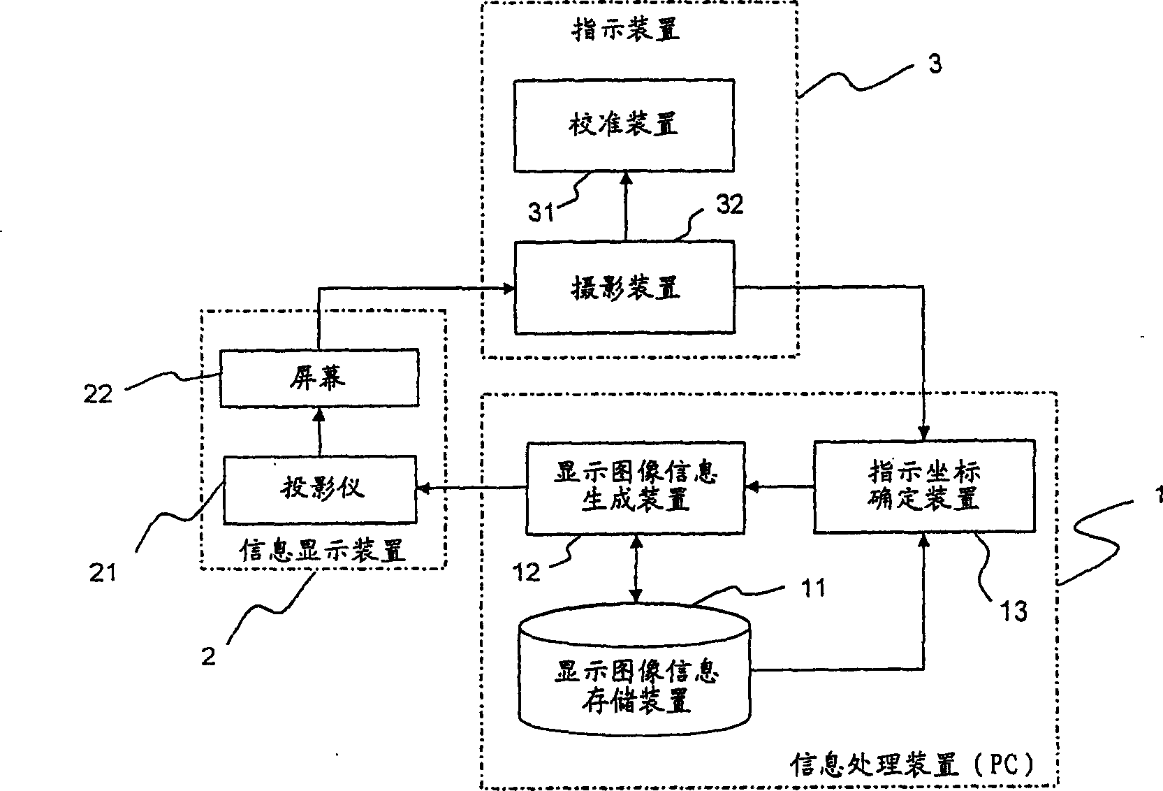
[0118] figure 1 It is a diagram showing constituent elements necessary for explaining the first embodiment, and the constituent elements are roughly divided into: a PC 1 as an information processing device; an information display device 2 that displays information output from the PC 1 ; and an image that instructs the information display device to display Pointing device 3 anywhere on it.
[0119] Also, as described above, it is assumed that a portable information terminal (a mobile phone with a camera, a digital camera with a communication function, a digital video camera with a communication function, etc.) having a photography function and a communication function is used as the pointing device 3 .
[0120] PC1 has: display image information storage device 11, which stores the image information of the image to be displayed; display image information generation device 12, which has the following function: while generating the image information that should be displayed at the...
Embodiment approach 2
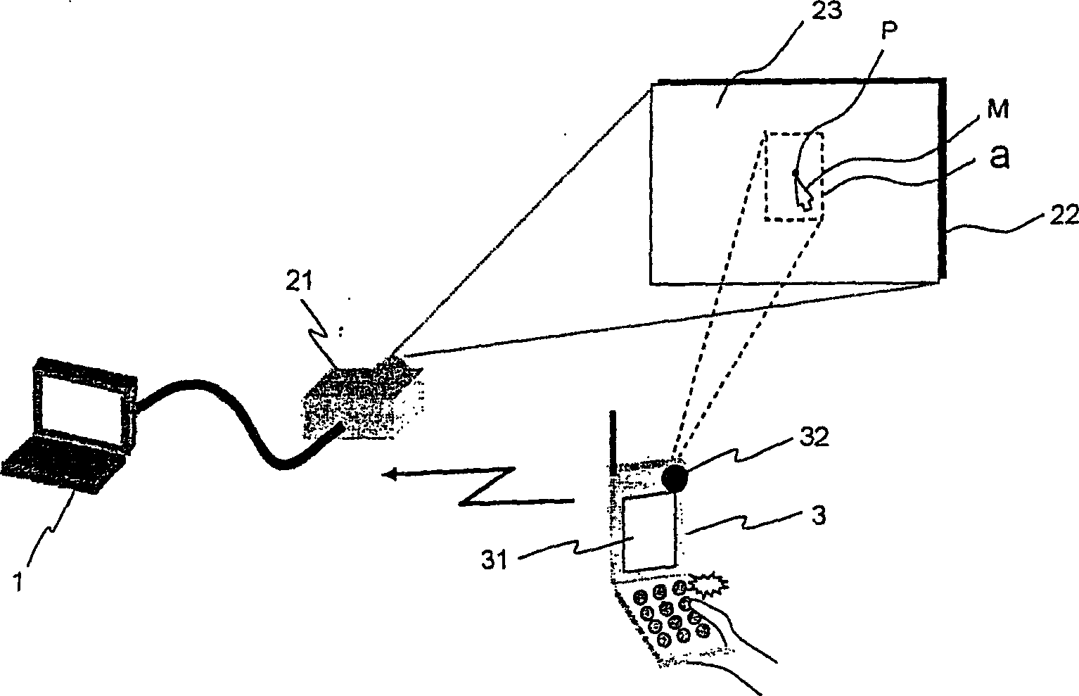
[0143] This second embodiment is an example in which the indicated position is acquired as a relative coordinate. In Embodiment 2, as in Embodiment 1, the following case will be described as an example: a projector 21 as an image display device is connected to PC1, and projector 21 projects data on PC1 onto a screen 22. , with respect to the display image 23 projected on the screen 22, an arbitrary position is determined by the pointing device 3, and the indicator M is displayed at the determined position.
[0144] Figure 5 It is a schematic diagram for explaining the constituent elements necessary for the second embodiment. Like the first embodiment, the constituent elements can be roughly divided into: PC1; a projector 21 connected to the PC1; Pointing device 3 in any position. Also in this second embodiment, the pointing device 3 will be described as the camera-equipped mobile phone 3 .
[0145] In Embodiment 2, PC 1 has: a display image information storage device 11 th...
Embodiment approach 3
[0178] This third embodiment enables the pointing device 3 to specify the pointing coordinates in the display image at high speed and with high precision by combining the above-mentioned first and second embodiments.
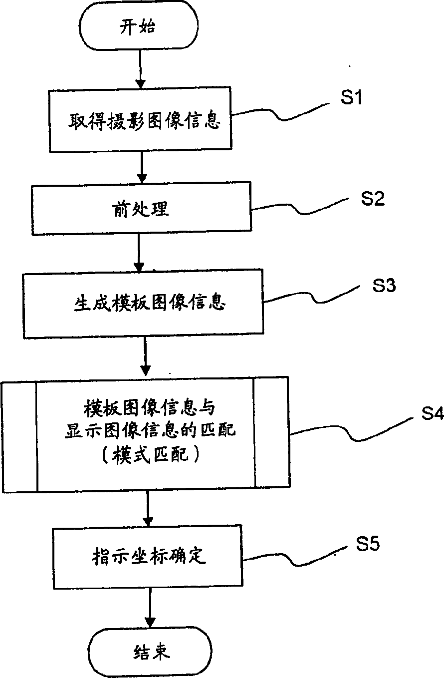
[0179] That is, in Embodiment 1, when the pointing device 3 determines the pointing coordinates, as image 3 As shown in the flow chart of FIG. 1 , when the photographed image information sent from the mobile phone with camera 3 is acquired (step S1), various correction processes such as distortion and brightness are first performed, and then various preprocessing such as scaling are performed (step S2 ), generate template image information (step S3) according to the photographed image information after the pre-processing. Perform pattern matching on the template image information and the display image information corresponding to the display image displayed at the time of shooting among the display image information stored in the display image information stora...
PUM
 Abstract
Description
Claims
Application Information
 - R&D
- Intellectual Property
- Life Sciences
- Materials
- Tech Scout
- Unparalleled Data Quality
- Higher Quality Content
- 60% Fewer Hallucinations
Browse by: Latest US Patents, China's latest patents, Technical Efficacy Thesaurus, Application Domain, Technology Topic, Popular Technical Reports.
© 2025 PatSnap. All rights reserved.Legal|Privacy policy|Modern Slavery Act Transparency Statement|Sitemap|About US| Contact US: help@patsnap.com