Elevator without mechanical room

A technology without mechanical rooms and elevators, which is applied in the directions of elevators, transportation and packaging in buildings, which can solve the problems of reduced service life of slings, difficulty in saving space in the height direction, difficulty in effective use of space and high speed, and achieve saving effect of space

Inactive Publication Date: 2006-10-11
HITACHI LTD
View PDF3 Cites 4 Cited by
  • Summary
  • Abstract
  • Description
  • Claims
  • Application Information

AI Technical Summary

Problems solved by technology

[0006] However, in the structure of Patent Document 1, since the 2-to-1 winding method is adopted, although there is no problem in the low-speed region, in the high-speed region, noise and vibration are likely to occur in the elevator car, so it is difficult to achieve high-speed
In the structure of Patent Document 2, since a thin motor with a small axial dimension is used, the planar area of ​​the lifting passage can be effectively reduced, but since the radial width of the thin motor increases, it is difficult to save space in the height direction
In addition, in the structure of Patent Document 2, although a 1-to-1 winding structure is adopted, the structure in which the sling is wound around the driving sheave (about 360 degrees) is adopted. If multiple slings need to be erected, With the above structure, the rope will be twisted and the life of the rope will be shortened, and special measures different from the usual shape are required to ensure the adhesion to the sheave, etc.
Furthermore, in the structure of Patent Document 3, although the driving sheave and the diverting pulley are set on the upper part of the lifting passage at the same height, and a fully wound (full-enclosed) structure is adopted, but because the balance weight side adopts The 2-to-1 winding structure increases the length of the sling and tends to sway due to mechanical resonance, making it difficult to achieve high speed
Moreover, in the structure of Patent Document 3, since the sheave is arranged at the corner of the lifting passage and driven by a single motor, it is difficult to realize effective use of space and high speed at the same time.

Method used


Image

  • Elevator without mechanical room
  • Elevator without mechanical room
  • Elevator without mechanical room

Examples


Embodiment Construction

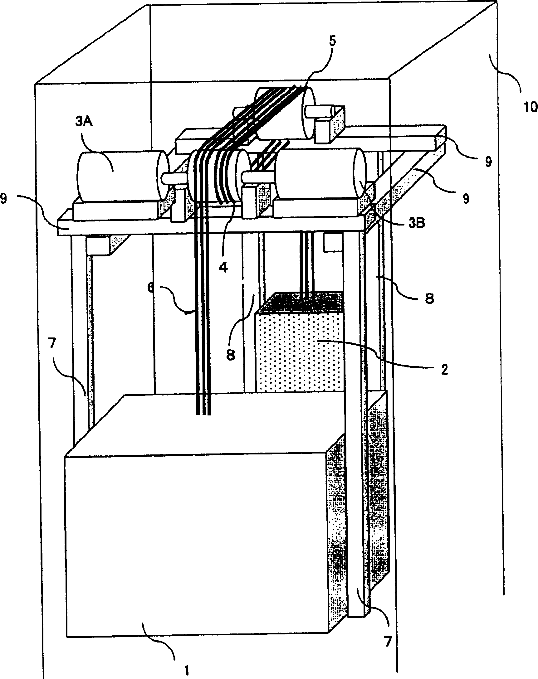
[0022] Embodiments of the present invention will be described below with reference to the drawings.

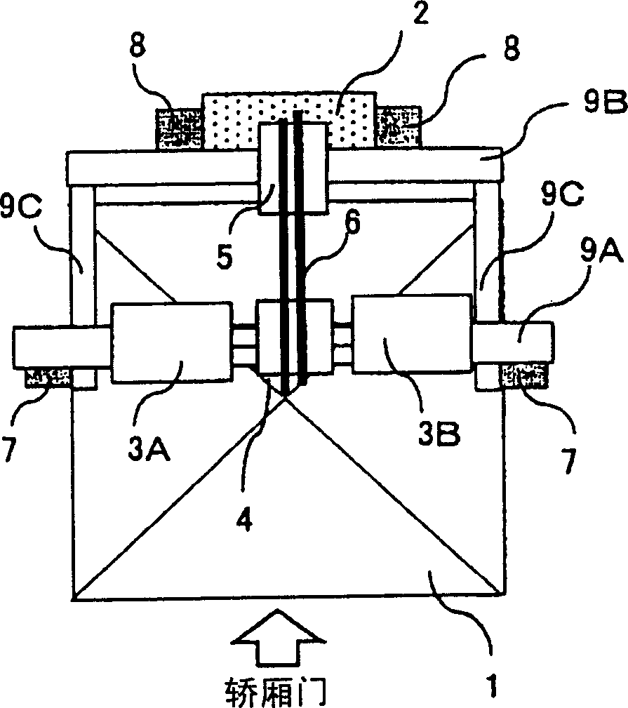
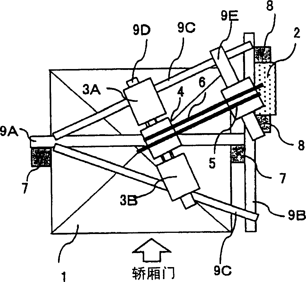
[0023] figure 1 is an overall configuration diagram of an elevator without a machine room as an embodiment of the present invention, figure 2 yes figure 1 The top view of the balance counterweight set at the rear of the elevator car, image 3 yes figure 1 The top view when the balance weight is set on the side of the elevator car, Figure 4 is a side view showing the relationship between the diameter of the drive sheave and the diameter of the sling, Figure 5 yes figure 1 An enlarged view of the driving sheave part, Figure 6 is a configuration diagram showing an embodiment of a power conversion device, Figure 7 yes Figure 6 The block diagram of the control circuit section, Figure 8 It is a test chart showing the measured torque waveform when the phase difference of the magnetic pole position is 0 degrees. Figure 9 It is a test chart showing the measured torque...


PUM


Abstract

A mechanical room-free elevator is provided. At least an elevator car (1), a balance weight (2), a sling (6), a drive sheave (4), and a motor (3) for driving the drive sheave (4) are provided inside the lift passage. and a diverting pulley (5), wherein a plurality of motors (3A, 3B) for driving the drive sheave (4) are arranged on both sides of the drive sheave (4), and the drive sheave (4) and The diverting pulley (5) adopts a 1-to-1 winding method, and one end of the sling (6) is wound on the elevator car (1), and the other end is wound on the balance weight (2) on. In this way, the elevator without a mechanical room can not only save the space at the top of the elevator car in the height direction of the hoistway, but also achieve high speed at the same time.

Description

technical field [0001] The invention relates to a machine-room-less elevator in which a driving device is arranged in an elevator passage. Background technique [0002] As a conventional elevator without a machine room, a traction sheave type elevator has been disclosed, such as the invention disclosed in Japanese Patent Laid-Open No. Hei 7-10434 of Patent Document 1, which is characterized in that the machine room is eliminated to reduce the occupied space. Space. In addition, for example, the invention disclosed in Japanese Patent Application Laid-Open No. 2002-80178 of Patent Document 2 uses a thin motor with a small axial dimension to reduce the planar area of ​​the lift passage. Furthermore, for example, the invention disclosed in Japanese Patent Application Laid-Open No. 2004-142853 of Patent Document 3 suspends the elevator car in a 1-to-1 winding manner and suspends the balance counterweight in a 2-to-1 winding manner. , thus setting the lifting stroke of the balan...

Claims


Application Information

Patent Timeline
Patent Type & Authority Applications(China)
IPC IPC(8): B66B9/00B66B11/04
Inventor 绫野秀树稻叶博美名仓宽和荒堀升藤野笃哉萩谷知文
Owner HITACHI LTD
Why Eureka
Try Eureka