Tri-state RF switch

一种射频开关、状态的技术,应用在电开关、触点、继电器等方向,能够解决增加器件复杂度等问题

Inactive Publication Date: 2006-10-11
SAMSUNG ELECTRONICS CO LTD
View PDF0 Cites 12 Cited by
  • Summary
  • Abstract
  • Description
  • Claims
  • Application Information

AI Technical Summary

Problems solved by technology

[0005] In the case of using a traditional RF switch, in order to realize that three output signals correspond to one input signal, two RF switches with two output signals need to be connected, thus increasing the complexity of the device

Method used


Image

  • Tri-state RF switch
  • Tri-state RF switch
  • Tri-state RF switch

Examples


Embodiment Construction

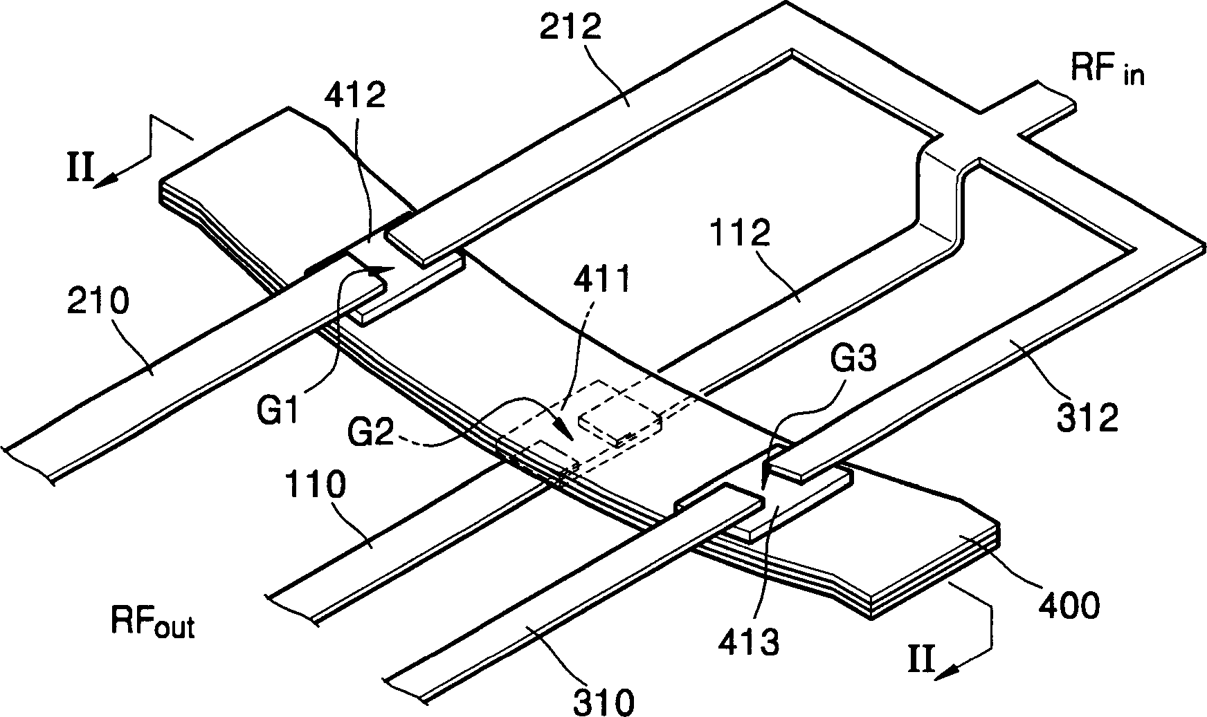
[0025] figure 1 is a schematic perspective view showing the structure of an RF switch according to an embodiment of the present invention. see figure 1 , the input signal line of the RF switch is divided into first to third input signal lines 112, 212 and 312, and the first to third Three gaps G1, G2 and G3. The first output signal line 110 and the second and third output signal lines 210 and 310 are located at different heights.

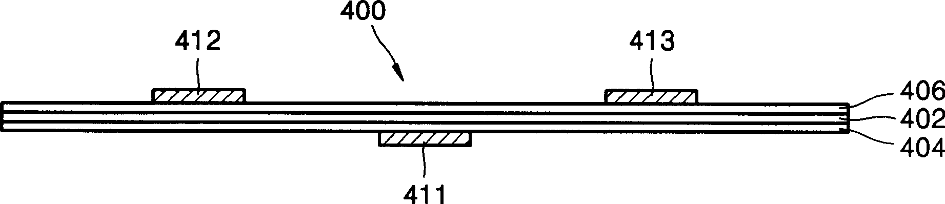
[0026] Between the first output signal line 110 and the other two output signal lines 210 and 310, a diaphragm 400 is formed across the first to third gaps G1, G2 and G3. The first to third metal pads 411, 412, and 413 corresponding to the first to third gaps G1, G2, and G3 are respectively formed on the diaphragm 400, and the metal pads 411, 412, and 413 can be connected at the corresponding input Power is transmitted between the signal wire and the output signal wire. The diaphragm 400 will be described later.

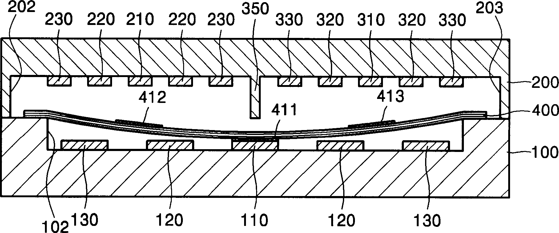
[0027] figure 2 is along f...


PUM


Abstract

A tri-state RF MEMS switch includes: a first well formed in a first substrate; a first input signal line and a first output signal line forming a first gap therebetween in the first well; a post bar forming a boundary between the second well and third well in the second substrate; a second input signal line and a second output signal line, and a third input signal line and a third output signal line forming a second gap and a third gap in the second well and the third well, respectively; and a membrane disposed between the first substrate and the second substrate such that the membrane crosses the first, second and third gaps, the membrane including a first conductive pad, a second conductive pad, and a third conductive pad thereon to face the first, second and third gaps, respectively.

Description

technical field [0001] The present invention relates to a three-state latching radio frequency (RF) switch, in particular, a radio frequency micro-electro-mechanical system (MEMS-micro electro-mechanical system) switch that locks one state in three states. Background technique [0002] Radio frequency (RF) microelectromechanical systems (MEMS) devices can be used in communications, radar, and wireless local area network (WLAN) technologies. RF MEMS devices include micromachined capacitors, inductors, RF switches, phase shifters, and tunable oscillators. These devices have better performance than devices made with previous technologies. For example, compared with a conventional FET field effect transistor or GaAs PIN diode switch (GaAs PIN diode switch), RF MEMS switches have characteristics such as low insertion loss, excellent signal separation, high linearity and low intermodulation. In particular, RF MEMS switches show excellent characteristics at high radio frequency r...

Claims


Application Information

Patent Timeline
Patent Type & Authority Applications(China)
IPC IPC(8): H01H59/00H01P1/10
CPCH01H2001/0042H01P1/127H01H59/0009H01H59/00H01L29/00
Inventor 崔蓥焦继伟王跃林邢向龙
Owner SAMSUNG ELECTRONICS CO LTD
Why Eureka
Try Eureka