Series radio-frequency micro-electromechanical switch amplified on basis of heat driving and preparation method of same

A micro-electromechanical, thermally driven technology, applied in the direction of generators/motors, processes for creating decorative surface effects, piezoelectric effect/electrostrictive or magnetostrictive motors, etc. Life reduction and other problems, to achieve the effect of preventing signal attenuation, high yield, and preventing damage to RF devices

Inactive Publication Date: 2010-04-14
SHANGHAI JIAO TONG UNIV
View PDF0 Cites 1 Cited by
  • Summary
  • Abstract
  • Description
  • Claims
  • Application Information

AI Technical Summary

Problems solved by technology

This kind of V-shaped beam has a simple design structure and obvious magnification effect, but it also has some defects: First, in order to obtain sufficient magnification, the angle between the two half-arms of the V-shaped beam needs to be as close to 180 degrees as possible, which brings several aspects. Problem: 1) Relatively large stress inside the beam affects the deformation of the beam; 2) Large stress will reduce the life of the device
At this point, using a V-beam design poses a big problem

Method used


Image

  • Series radio-frequency micro-electromechanical switch amplified on basis of heat driving and preparation method of same
  • Series radio-frequency micro-electromechanical switch amplified on basis of heat driving and preparation method of same
  • Series radio-frequency micro-electromechanical switch amplified on basis of heat driving and preparation method of same

Examples


Embodiment 1

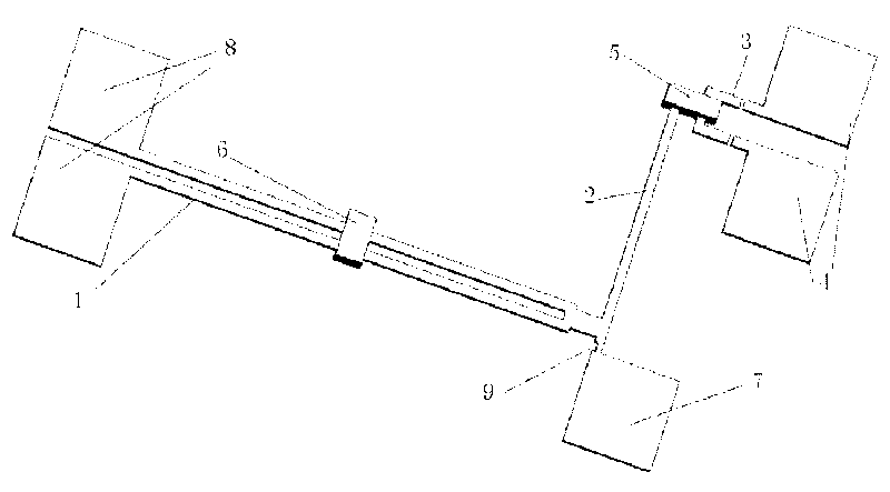
[0043] Such as figure 1As shown, this embodiment includes: a thermally driven arm 1, an amplifying arm 2, a contact block 4, an isolation block 5, a fixed end of the amplifying arm 2 and a fixed end of the thermally actuated arm 1, wherein: two thermally actuated arms 1 are parallel to each other and one end It is fixedly connected with one end of the amplifying arm 2, the other ends of the two thermal driving arms 1 are respectively connected with the fixed ends of the two thermal actuating arms 1, and the end of the amplifying arm 2 near the thermal actuating arm 1 is connected with the fixed end of the amplifying arm 2, The other end of the amplifying arm 2 is connected with the isolation block 5 , and the isolation block 5 is arranged opposite to the two contact blocks 4 .

[0044] In this embodiment: the length of the connecting contact 3 is 50 μm, and the width is 30 μm; the length of the thermally driven arm 1 is 500 μm; the length of the amplifying arm 2 is 250 μm; the...

Embodiment 2

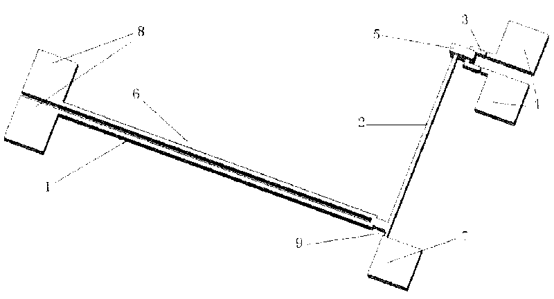
[0054] Such as figure 2 As shown, this embodiment includes: a thermally driven arm 1, an amplifying arm 2, a contact block 4, an isolation block 5, a fixed end of the amplifying arm 2 and a fixed end of the thermally actuated arm 1, wherein: two thermally actuated arms 1 are parallel to each other and one end It is fixedly connected with one end of the amplifying arm 2, the other ends of the two thermal driving arms 1 are respectively connected with the fixed ends of the two thermal actuating arms 1, and the end of the amplifying arm 2 near the thermal actuating arm 1 is connected with the fixed end of the amplifying arm 2, The other end of the amplifying arm 2 is connected with the isolation block 5 , and the isolation block 5 is arranged opposite to the two contact blocks 4 .

[0055] In this embodiment: the length of the connecting contact 3 is 80 μm, and the width is 50 μm; the length of the thermally driven arm 1 is 800 μm; the length of the amplifying arm 2 is 500 μm; t...

Embodiment 3

[0066] The length of the connecting contact 3 is 80 μm, and the width is 50 μm; the length of the thermal driving arm 1 is 800 μm; the length of the amplification arm 2 is 500 μm; the thickness is 30 μm, and the line width of each part is 20 μm; the length of the anti-short circuit block 6 is 800 μm, the thickness is 50 μm, and the width is 80 μm ; The length of the SU8 spacer 5 is 80 μm, the thickness is 50 μm, and the width is 50 μm; the fulcrum distance is 50 μm; the gap distance is 8 μm.

[0067] Such as figure 2 As shown, in this embodiment, the structure of the switch is basically the same as that of Embodiment 2. The difference is that the anti-short circuit block 6 wraps the entire heating arm, which can enhance the stability of the heating arm and prevent the heating arm from being deformed by force. In addition, this will reduce the cooling rate of the switch, and the result is that the switch turns on faster and the switch turns off slower.

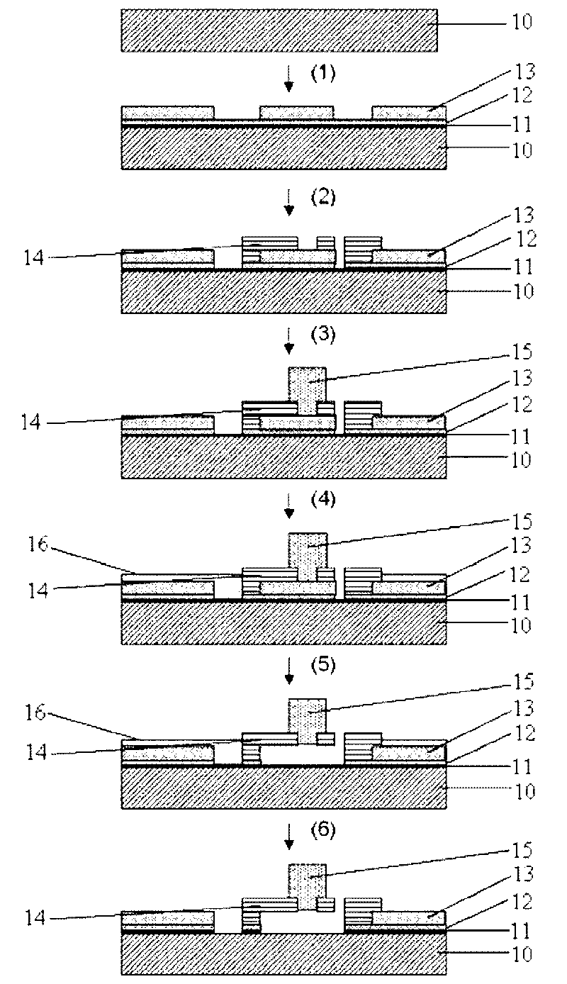
[0068] Such as ima...


PUM

PropertyMeasurementUnit
thicknessaaaaaaaaaa
lengthaaaaaaaaaa
thicknessaaaaaaaaaa

Abstract

A series radio-frequency micro-electromechanical switch amplified on basis of heat driving belongs to the technical field of radio-frequency micro-electromechanical systems, and comprises two heat driving arms, an amplifying arm, two contact blocks, an isolating block, an amplifying arm fixed end and two heat driving arm fixed ends, wherein the two heat driving arms are arranged in parallel, one end of each heat driving arm is fixedly connected with one end of the amplifying arm, the other end of each heat driving arm is connected with the two heat driving arm fixed ends, one end of the amplifying arm close to the heat driving arms is connected with the amplifying arm fixed end, and the other end of the amplifying arm is connected with the isolating block which is arranged oppositely to the two contact blocks. The invention has the advantages of small size, wide switch travel, low driving voltage, isolation between radio-frequency signals and driving current, simple process, high rate of finished products and the like.

Description

technical field [0001] The invention relates to a device in the technical field of radio-frequency micro-electro-mechanical systems, in particular to a serial radio-frequency micro-electro-mechanical switch based on thermally driven amplification and a preparation method thereof. Background technique [0002] In order to meet the development requirements of wireless communication devices, radio frequency components are developing toward miniaturization and integration. At the same time, the device should meet the requirements of insertion loss, isolation, impedance matching, etc. The combined research of MEMS (micro-electro-mechanical systems) technology and RF (radio frequency) technology provides a new solution for the above problems. RF-MEMS devices can increase isolation, reduce interconnection loss, and can be manufactured with quasi-three-dimensional planar processing technology compatible with existing semiconductor processes. RF-MEMS switches combine the advantages...

Claims


Application Information

Patent Timeline
Patent Type & Authority Applications(China)
IPC IPC(8): H01P1/10B81B7/02B81C1/00
Inventor 陈迪黄闯胡志军陈翔朱军
Owner SHANGHAI JIAO TONG UNIV
Why Eureka
Try Eureka