
Printer head using a radio frequency micro-electromechanical system (RF MEMS) sprayer

a printing head and micro-electromechanical technology, applied in the field of printing head, can solve the problems of low printing speed, complex process, and difficulty in controlling the amount of ink discharged by the inkjet printer head, and achieve the effects of simple structure, easy and precise regulation of ink discharge, and fast discharging reaction rate of ink

Active Publication Date: 2006-08-01
SAMSUNG ELECTRONICS CO LTD
View PDF7 Cites 1 Cited by
  • Summary
  • Abstract
  • Description
  • Claims
  • Application Information

AI Technical Summary

Benefits of technology

[0017]It is a feature of an embodiment of the present invention to attempt to solve at least some of the above problems and / or disadvantages and to provide a printer head using an RF MEMS sprayer that is capable of a fast discharging reaction rate of ink, an easy and precise regulation of discharging ink and a simple structure to permit high integration of nozzles.
[0024]In the RF MEMS sprayer, the liquid inlet prevents a liquid inside the inner pressure chamber from flowing back into the liquid chamber when an inner pressure of the inner pressure chamber is increased by the cavity resonator.

Problems solved by technology

A conventional inkjet printer head using the above-described piezoelectric body has a disadvantage of a low printing speed due to an operating speed limit of the piezoelectric body.
In addition, such a conventional inkjet printer head has difficulty in controlling an amount of ink discharged.
Further, the manufacturing process is complex and the structure is overly complicated thereby rendering high integration difficult.
In printing a color image, if an amount of ink discharged is too great, then the printed image becomes dark overall, thereby lowering a resolution of the printed image.
Alternately, if an amount of ink discharged is too small, an output image becomes unclear or a quality of the image is degraded since some of the nozzles do not discharge any ink.
The thermal driving inkjet printer head, however, is severely affected by ambient temperature and humidity conditions.
Under high temperature and humidity conditions, such a printer head has problems in that an output image is too dark.
Further, such a printer head has problems in that it is not easy to precisely regulate an amount of ink discharged and a discharging reaction rate of ink is low due to a limited operating reaction rate of the thermal resistor.
Moreover, the printer head has additional problems in that the structure thereof is so complicated that it is not easy to highly integrate a plurality of nozzles, thereby further limiting the resolution of an output image.

Method used


Image

  • Printer head using a radio frequency micro-electromechanical system (RF MEMS) sprayer
  • Printer head using a radio frequency micro-electromechanical system (RF MEMS) sprayer
  • Printer head using a radio frequency micro-electromechanical system (RF MEMS) sprayer

Examples


first embodiment

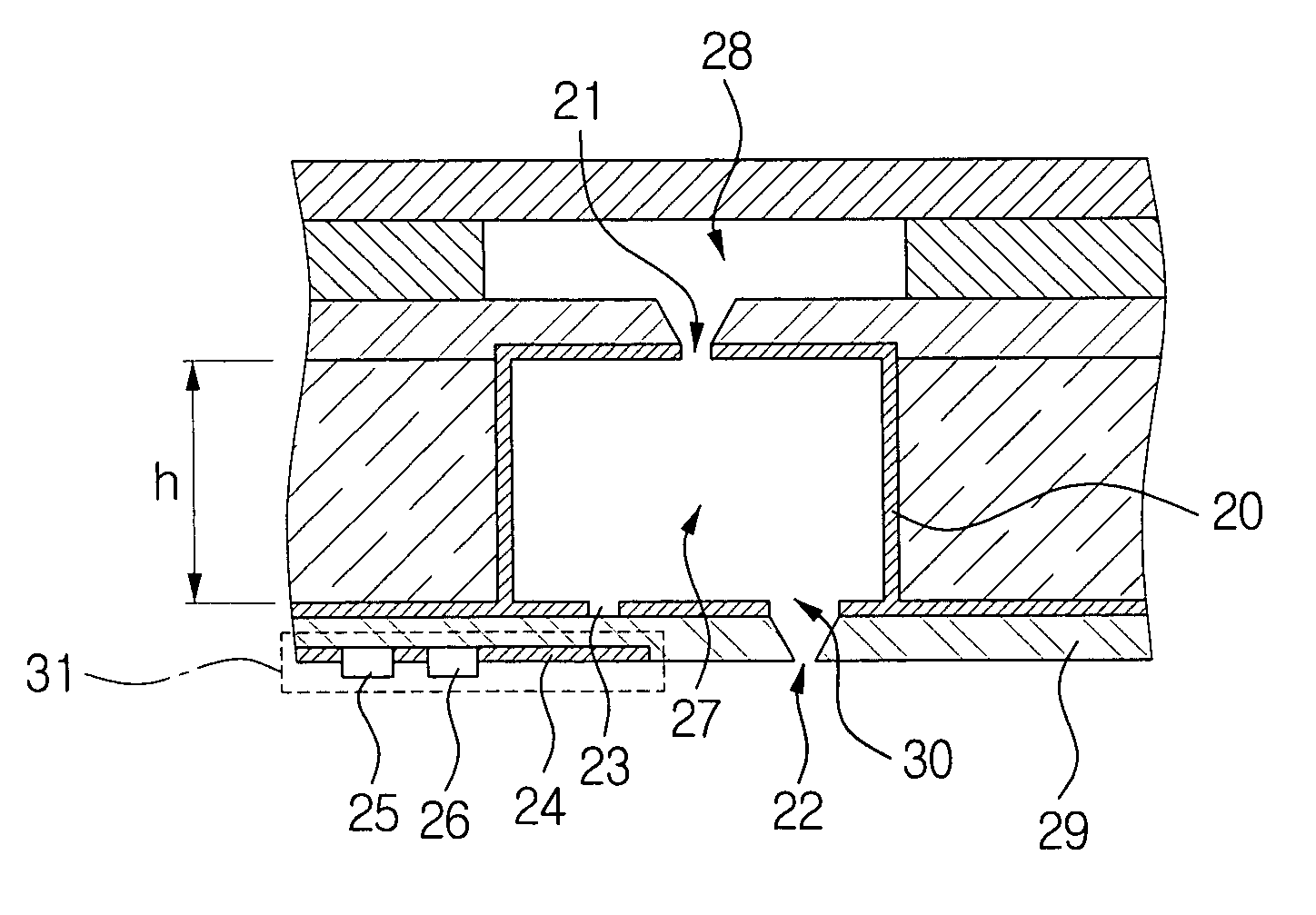
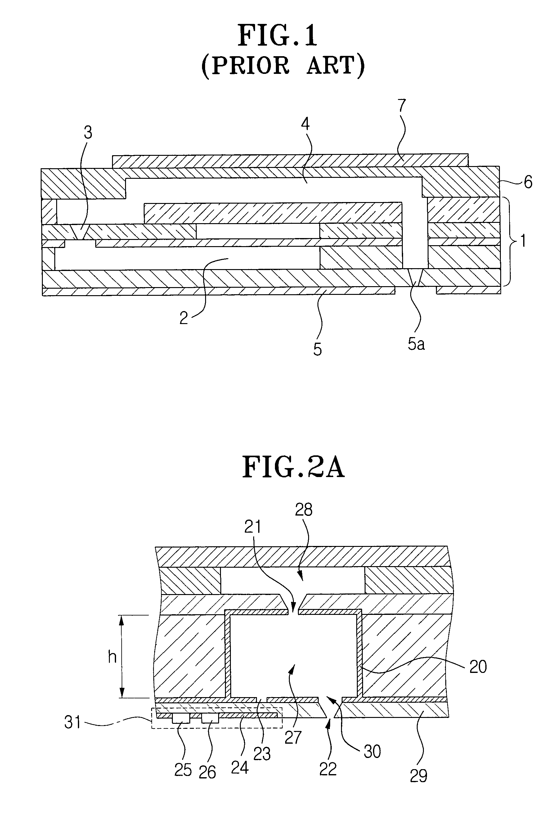
[0034]FIG. 2A illustrates a cross-sectional view of a printer head using an RF MEMS sprayer in accordance with the present invention. FIG. 2B illustrates a bottom view of the printer head in FIG. 2A.

[0035]As shown in FIGS. 2A and 2B, an RF MEMS sprayer includes an inner pressure chamber 27 disposed inside thereof, a liquid inlet 21 disposed at an upper side of the inner pressure chamber 27, and a cavity resonator 20 having a coupling slot 23 for receiving a cavity resonance frequency signal, and a liquid outlet 30 disposed at a lower side of the inner pressure chamber.

[0036]The MEMS sprayer 20 further includes a substrate 29 having a nozzle 22 at a position corresponding to the liquid outlet 30. The substrate 29 is welded to the lower side of the cavity resonator 20 and a signal transmitting unit 31 is welded under the substrate 29.

[0037]The signal transmitting unit 31 includes a signal input terminal 24 disposed at a position facing the coupling slot 23 with the substrate 29 positi...

second embodiment

[0051]With reference to FIGS. 3A and 3B, a printer head using an RF MEMS sprayer in accordance with the present invention will now be described.

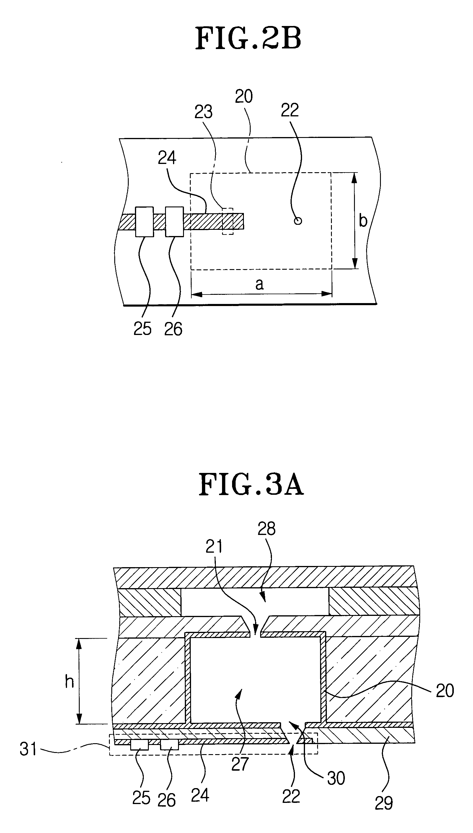
[0052]FIG. 3A illustrates a cross-sectional view of the printer head using the RF MEMS sprayer according to a second embodiment of the present invention. FIG. 3B illustrates a bottom view of the printer head in FIG. 3A.

[0053]As shown, the printer head according to the second embodiment has a similar structure as the printer head according to the first embodiment except that the coupling slot 23 is omitted from the second embodiment and a signal input terminal 24 is extended to a nozzle 22.

[0054]In operation, a cavity resonance frequency signal from a signal amplifier 26 is inputted to a cavity resonator 20 through a liquid outlet 30. In all other respects, the printer head using the RF MEMS sprayer having the structure of the second embodiment operates the same as the printer head according to the first embodiment.

[0055]More specifically, a ...


PUM


Abstract

A printer head using a radio frequency micro-electromechanical system (RF MEMS) sprayer includes an inner pressure chamber having a liquid inlet and a liquid outlet; a cavity resonator surrounding the inner pressure chamber, wherein the cavity resonator inputs a predetermined cavity resonance frequency signal to increase an inner pressure of the inner pressure chamber; a signal transmitting unit for generating the predetermined cavity resonance frequency signal and for inputting the generated cavity resonance frequency signal into the inner pressure chamber through the cavity resonator in response to an external input control signal; and a liquid chamber for supplying a liquid, wherein the liquid inlet and the liquid outlet each extend through the inner pressure chamber and the cavity resonator so that when an inner pressure of the inner pressure chamber is increased by the cavity resonator, a liquid from within the inner pressure chamber is ejected.

Description

BACKGROUND OF THE INVENTION[0001]1. Field of the Invention[0002]The present invention relates to an inkjet printer head. More particularly, the present invention relates to a printer head using a radio frequency micro-electromechanical system (RF MEMS) sprayer including an RF cavity resonator.[0003]2. Background of the Related Art[0004]In general, a spraying device for spraying a droplet of a liquid may be used in an inkjet printer head, a MEMS cooling device, or the like. A driving method for an inkjet printer head may be classified into a mechanical driving method using a piezoelectric element or a thermal driving method.[0005]FIG. 1 illustrates a cross-sectional view of a conventional printer head using a piezoelectric element.[0006]As shown in FIG. 1, a conventional printer head using a piezoelectric element includes a plate-shaped piezoelectric body 7, a vibrating plate 6 disposed under the piezoelectric body 7 for converting a longitudinally expanding motion of the piezoelectr...

Claims


Application Information

Patent Timeline
Patent Type & Authority Patents(United States)
IPC IPC(8): B41J2/135B41J2/05B41J2/015B41J2/045B41J2/14B41J2/235B81B7/00
CPCB41J2/14008B41J2/235
Inventor SONG, IN-SANG
Owner SAMSUNG ELECTRONICS CO LTD
Learn More