
Oil-hydraulic type automatic shutoff valve water-saving structure

Inactive Publication Date: 2006-09-21
LIYIH MAKE
View PDF9 Cites 9 Cited by
  • Summary
  • Abstract
  • Description
  • Claims
  • Application Information

AI Technical Summary

Benefits of technology

[0003] It is, therefore, the primary purpose of the present invention to provide an oil-hydraulic type automatic shutoff valve water-saving structure, including a valve housing having a separation portion disposed therein to divide a water inlet tube, a water outlet port, and a valve chamber thereby and form a water-collecting space, a preset channel, and a water outlet channel respectively at the interior of the valve housing therein so that when an oil-hydraulic type automatic shutoff valve is mounted into the valve chamber thereof, water flow accommodated at the water-collecting space therein can be individually separated from an oil storage portion of the automatic shutoff valve, precisely preventing the automatic shutoff valve from soaking in the water flow and causing the problem of water leakage into an outer cap thereof, and efficiently maintaining the hydraulic pressure and the lubrication of the oil accommodated at the oil storage portion therein to facilitate a smooth and accurate push operation of the present invention thereof and extend the using life time thereof.
[0004] It is, therefore, the second purpose of the present invention to provide an oil-hydraulic type automatic shutoff valve water-saving structure wherein via an adjusting cylinder of a second central shaft, a cavity of a first central shaft, and a cylindrical channel of a pressure valve that are reciprocally communicated for the accommodation of a regulating pin with a tapered regulating needle therein, the regulating pin can be speedily and accurately adjusted to modify the distance between the tapered regulating needle and a thru-hole section of the second central shaft, permitting easy and precise regulation of the automatic shutoff valve to control the time-length and amount of water discharge according to the need of a user to achieve the best using state and save water resource thereby.

Problems solved by technology

Thus, part of the water flow tends to leak into an outer cap 41 and mix up with oil A accommodated therein, which, affecting the interior pressure and reducing the lubrication effect of the oil thereof, can lead to an awkward and difficult push operation of the conventional oil-hydraulic automatic shutoff valve thereof.

Method used


Image

  • Oil-hydraulic type automatic shutoff valve water-saving structure
  • Oil-hydraulic type automatic shutoff valve water-saving structure
  • Oil-hydraulic type automatic shutoff valve water-saving structure

Examples


Embodiment Construction

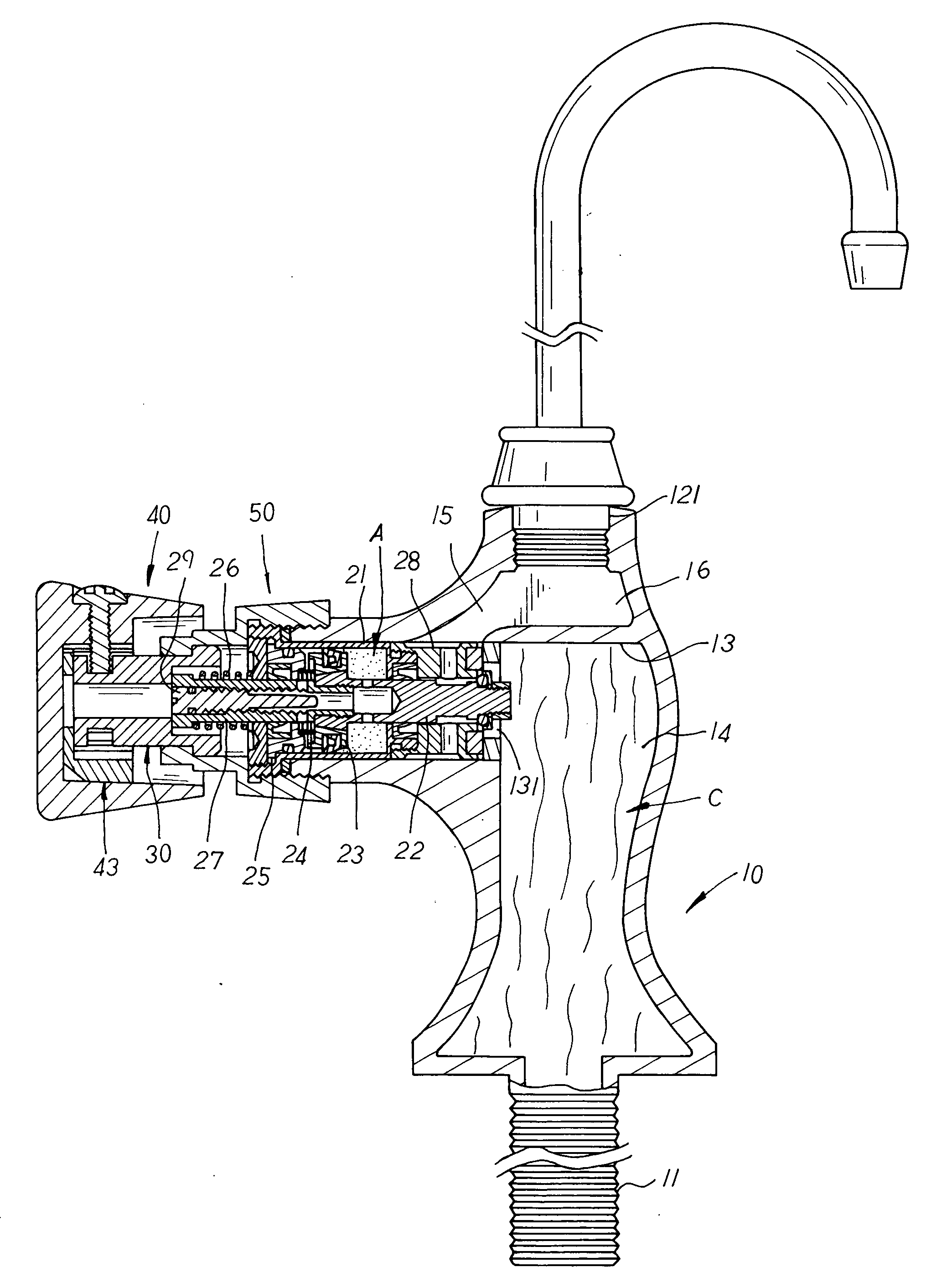
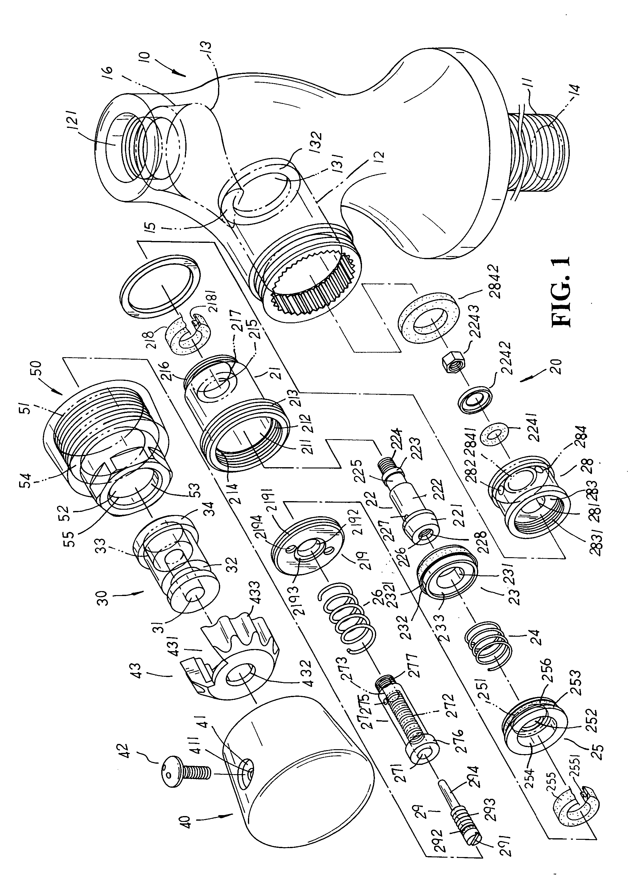
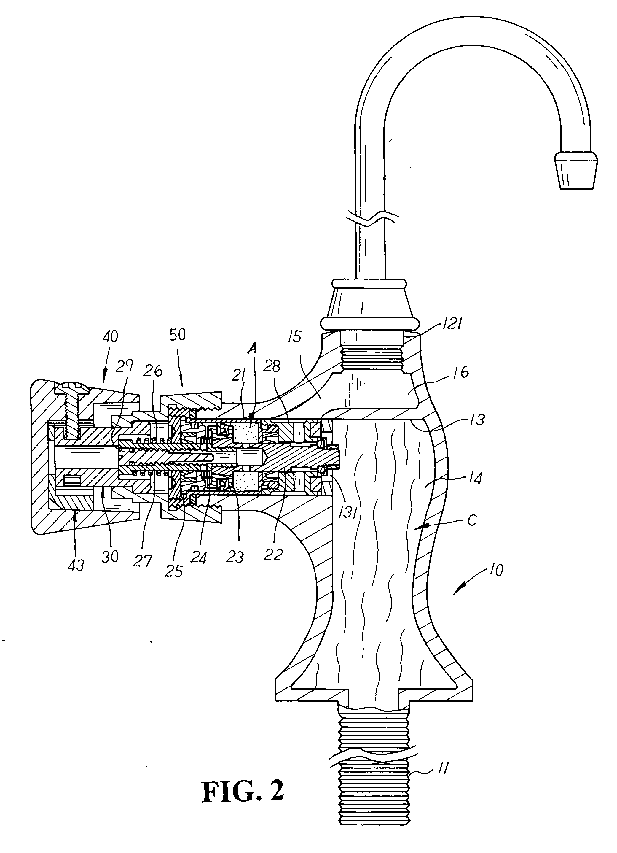
[0009] Please refer to FIG. 1 showing an exploded perspective view of the present invention. The present invention is related to an oil-hydraulic type automatic shutoff valve water-saving structure, comprising a valve housing 10, an automatic shutoff valve 20, a pressure valve 30, a press head 40, and a fixing connector 50. The valve housing 10 has a water inlet tube 11 and a water outlet port 121 respectively disposed at the bottom and top ends thereon, a valve chamber 12 extending transversely at one lateral side thereon, and a separation portion 13 disposed at a predetermined position of the interior therein wherein the separation portion 13 is made in a reversed L-shape, and both ends of which are respectively connected to the inner wall at one side of the valve chamber 12 and to the inner wall of the valve housing 10 thereof so as to divide the water inlet tube 11, the water outlet port 121, and the valve chamber 12 thereby and form a water-collecting space 14, a preset channel...


PUM


Abstract

An oil-hydraulic type automatic shutoff valve water-saving structure comprises a valve housing having a separation portion disposed therein to divide a water inlet tube, a water outlet port, and a valve chamber thereby and form a water-collecting space, a preset channel, and a water outlet channel respectively at the interior of the valve housing therein with an opening defined by a stop seat disposed in vertical alignment with one end of the separation portion thereof. Into the valve chamber of the valve housing thereof is mounted an oil-hydraulic type automatic shutoff valve composed of an outer cap, a first central shaft, an inner positioning block, a small spring, a retaining block, a big spring, a second central shaft, a water inlet valve and a regulating pin. Via the aforementioned structure, water flow accommodated at the water-collecting space therein can be individually separated from an oil storage portion of the automatic shutoff valve, precisely preventing the automatic shutoff valve from soaking in the water flow and causing the problem of water leakage into the outer cap thereof, and efficiently maintaining the hydraulic pressure and the lubrication of the oil accommodated at the oil storage portion therein to facilitate a smooth and accurate push operation of the present invention thereof.

Description

BACKGROUND OF THE INVENTION [0001] The present invention is related to an oil-hydraulic type automatic shutoff valve water-saving structure, including a valve housing having a separation portion disposed therein to divide a water inlet tube, a water outlet port, and a valve chamber thereby and form a water-collecting space, a preset channel, and a water outlet channel respectively at the interior of the valve housing therein so that when an oil-hydraulic type automatic shutoff valve is mounted into the valve chamber thereof, water flow accommodated at the water-collecting space therein can be individually separated from an oil storage portion of the automatic shutoff valve, precisely preventing the automatic shutoff valve from soaking in the water flow and causing the problem of water leakage into an outer cap thereof, and efficiently maintaining the hydraulic pressure and the lubrication of the oil accommodated at the oil storage portion therein to facilitate a smooth and accurate ...

Claims


Application Information

Patent Timeline
IPC IPC(8): F16K31/12F16K21/10F16K31/60
CPCF16K21/10E03C1/04
Inventor LIAO, CHING-HSIANG
Owner LIYIH MAKE
Learn More