
Display driving device, display apparatus, and method of driving the same

a technology of display memory and driving device, which is applied in the field of display, can solve the problems of difficult programming of the regulator by the internal controller, large power consumption of the display, and inability to achieve the effect of minimizing the effect of voltage drop, minimizing the error of data read from the display memory, and easy and precise changes

Inactive Publication Date: 2006-10-03
ROHM CO LTD
View PDF5 Cites 0 Cited by
  • Summary
  • Abstract
  • Description
  • Claims
  • Application Information

AI Technical Summary

Benefits of technology

[0019]It is therefore an object of the invention to provide a method of easily and precisely regulating the frequency of a display driving device according to the display mode selected, even when it is a low tone mode and a partial display mode.
[0022]It is a still further object of the invention to provide a method of driving a display driving device which is little affected by a voltage drop in the supply voltage immediately after row selection during a read of data from the display memory.
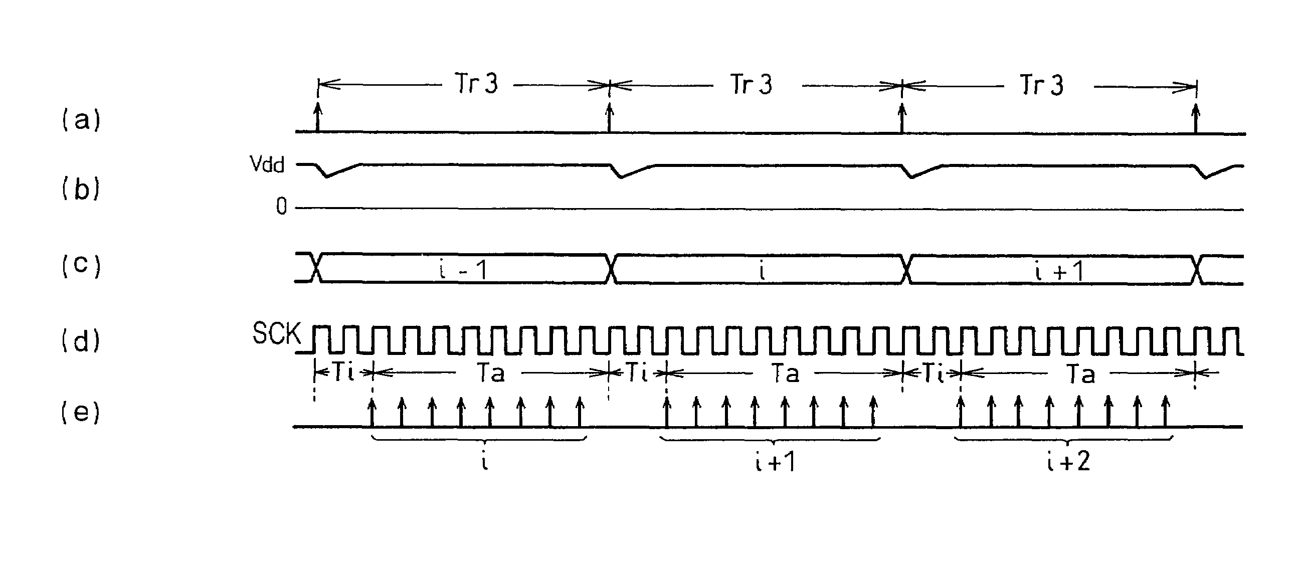
[0028]The row selection period of the invention consists of an accessing period for accessing the display memory and an idling period in which access is not made. Consequently, in a low tone mode or in a partial display mode where the display driving device is run at a reduced frequency, the frequency may be easily and precisely changed by changing the idling period.
[0029]The idling period lasts an integral multiple of the system clock such that at least one part of the idling period is provided at the beginning of the row selection period and prior to the accessing period. If this idling period is set to cover a voltage drop that takes place immediately after row selection, the effect of the voltage drop can be minimized, thereby minimizing errors in the data read from the display memory. Since the timing of the column output is not synchronized with the memory access, power consumption takes place randomly over the driving period, resulting in only negligible fluctuations in the supply voltage.
[0030]In the invention, the number of clocks n defining the idling period, and hence the row selection period, may be arbitrarily changed by a control signal. By increasing n, the row selection period may be easily extended to reduce the frequency of accessing the display memory as well as the frequency of selecting a row line (row line selection frequency). This can be done in such a way that part of n clocks of the idling period precedes the row selection period, with the preceding clocks variable in accordance with the display mode (e.g. low tone mode and / or partial display mode) to reduce the power consumed in the memory access and in driving the display driving device. The invention thus allows easy and precise regulation of the driving frequency of the display driving device by merely changing the number n of the idling clocks without changing the frequency of the system clock.

Problems solved by technology

This inevitably entails greater power consumption by a display.
It is then necessary to provide means for precisely regulating the time constant (referred to as time constant regulator) of the clock generator 35 over a wide range of frequency, which is not easy.
If, however, the clock generator 35 is provided with an external time constant regulator, it is not possible to program the regulator by an internal controller such as CPU to automatically generate a desired time constant depending on different display modes.
However, since such a frequency divider has a frequency division ratio m, where m is an integer, it can only change the clock frequency by a factor of 1 / m, failing to provide fine regulation of the driving frequency.
The charging currents inevitably results in a further disadvantage that it causes a voltage drop due to the impedance of the LCD panel.
In portable apparatuses utilizing an LCD panel, the supply voltage is provided by a common battery, that the voltage drop pertinent to the LCD driving device, results in the voltage drops in other components such as display memory.
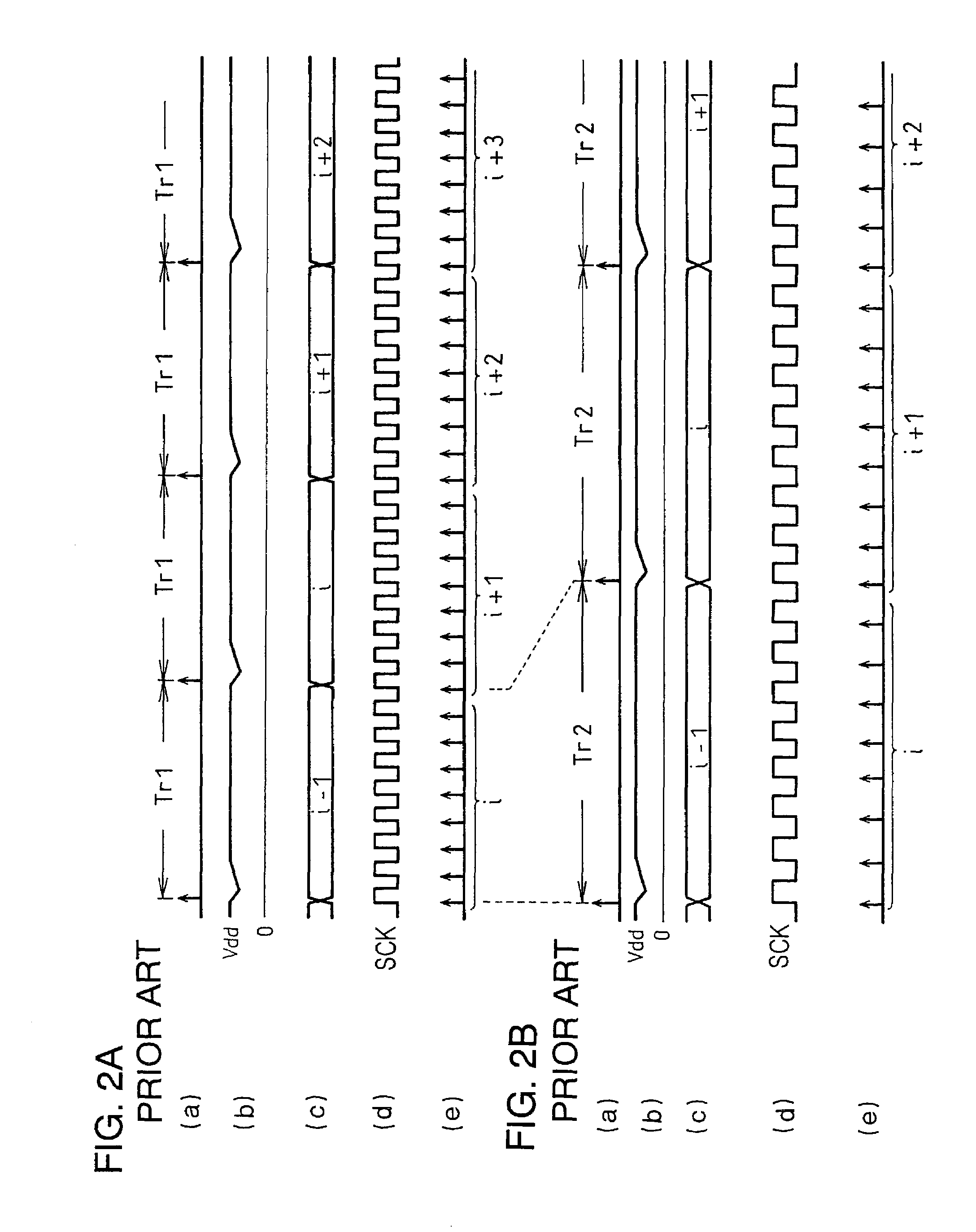
In the conventional LCD driving device, the voltage drop can cause an erroneous display data read from the display memory 12, since display data is retrieved from the display memory 12 in the row selection period Tr1 and Tr2 but it is difficult to maintain a minimum necessary operational voltage for the read if such voltage drop takes place.

Method used


Image

  • Display driving device, display apparatus, and method of driving the same
  • Display driving device, display apparatus, and method of driving the same
  • Display driving device, display apparatus, and method of driving the same

Examples


Embodiment Construction

[0036]The invention will now be described in detail by way of example with reference to the accompanying drawings. The invention, however, is not limited to the examples shown herein, but may be modified within the scope of the invention. For example the invention may be applied equally well to other types of display apparatus such as an organic electro-luminescence apparatus.

[0037]Referring now to FIG. 3, there is shown an LCD driving device implementing the invention. FIGS. 4A and 4B are timing diagrams illustrating operation of the LCD driving device of FIG. 3.

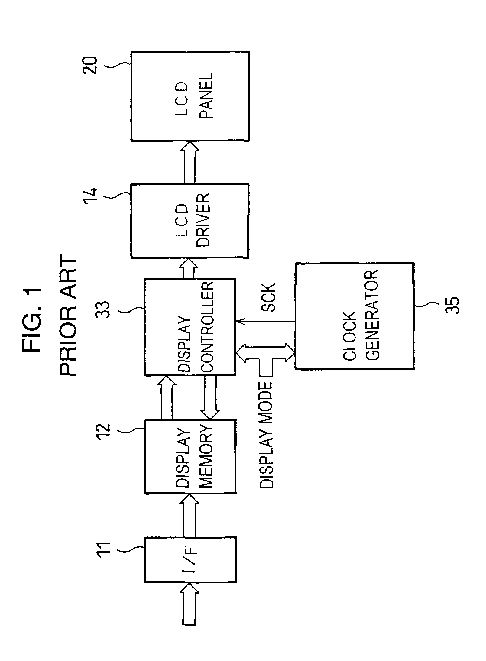
[0038]The LCD driving device includes an interface 11, a display memory 12, an LCD driver 14, and an LCD panel 20, as shown in FIG. 3, which can be the same as corresponding elements shown in FIG. 1.

[0039]A depression of voltage (hereinafter referred to as voltage depression) takes place immediately after each row selection, which can influence on display data read from the display memory 12. In order to minimize this influ...


PUM

PropertyMeasurementUnit
timeaaaaaaaaaa
frequencyaaaaaaaaaa
poweraaaaaaaaaa

Abstract

A display driving device adapted to output a column driving voltage to a sequentially selected one of row terminals of a display panel during a respective row selection period. The row selection period includes an accessing period for accessing a display memory and an idling period in which no access is made. At least a portion of the idling period may be provided prior to the accessing period. The idling period may be regulated in accordance with the display mode chosen.

Description

FIELD OF THE INVENTION[0001]The invention relates to a display such as a liquid crystal display (LCD) and an electro-luminescence (EL) display operable at a reduced power in accordance with the display mode chosen. The invention also relates to a method of driving a display and a display driving device for use in such display.BACKGROUND OF THE INVENTION[0002]Display means including LCD are widely used in many portable electronic apparatuses such as, mobile phones personal handyphone systems (PHSs), and personal digital assistants (PDAs).[0003]LCD used in these electronic apparatuses are increasingly equipped with a larger display panel having an increased number of tone levels in order to improve the visibility of information on the LCD. This inevitably entails greater power consumption by a display. Power saving is important for a portable electronic apparatus since it directly affects the operable hours of the apparatus if it is powered by a battery.[0004]In order to save energy, ...

Claims


Application Information

Patent Timeline
Patent Type & Authority Patents(United States)
IPC IPC(8): G09G3/36G02F1/133G09G3/20G09G5/18G09G5/36
CPCG09G5/36G09G3/3611G09G2330/021
Inventor NAIKI, TAKASHI
Owner ROHM CO LTD
Learn More