
Positive feedback abnormal protection circuit

A technology of abnormality protection and positive feedback, which is applied in the direction of electric light sources, electrical components, lighting devices, etc., can solve the problems of failure to consider the protection function of abnormal state, failure to meet the Energy Star standard, failure to realize shutdown action, etc., to achieve improved Effects of protecting performance and improving reliability

Active Publication Date: 2006-10-11
DONGYANG TOSPO LIGHTING
View PDF0 Cites 9 Cited by
  • Summary
  • Abstract
  • Description
  • Claims
  • Application Information

AI Technical Summary

Problems solved by technology

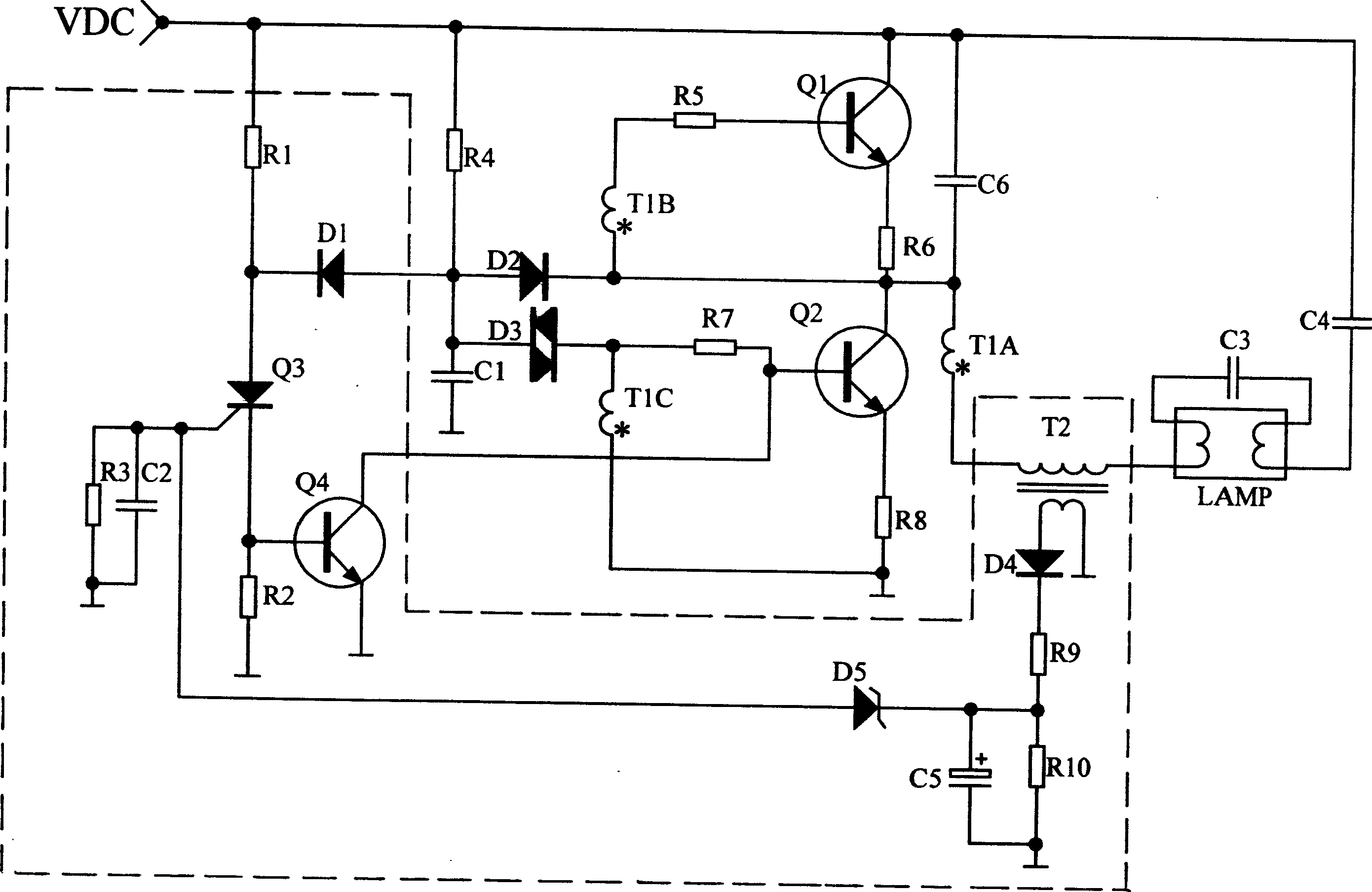
[0004] We know that bipolar transistors work in the switching state in the half-bridge oscillating DC / AC converter circuit, because in the prior art, the abnormal protection circuit is to reduce the Q of the lower bridge arm transistor of the DC / AC converter. 2 The voltage between the base and the emitter, instead of applying a reverse voltage to stop the vibration, therefore cannot achieve a fast and reliable shutdown action; in addition, the abnormal protection circuit used in the prior art is generally limited to overcurrent protection (when the lamp occurs In case of an air leak, use the figure 2 Medium output transformer T 2 The voltage generated by the secondary winding triggers the protection actuator Q 3 Complete protection; or through the DC / AC converter lower bridge arm transistor Q 2 Emitter resistance R 8 Sampling the current, and then converting it into a voltage to trigger the protection device to complete the protection), without considering the protection function of the abnormal state such as the overvoltage of the lamp tube and the rectification state, so that its application is limited to a certain extent, and it cannot meet the needs of energy sources. star standard

Method used


Image

  • Positive feedback abnormal protection circuit
  • Positive feedback abnormal protection circuit
  • Positive feedback abnormal protection circuit

Examples


Embodiment Construction

[0034] refer to figure 1 , 2 , a general fluorescent lamp electronic ballast includes a rectifier circuit, a DC / AC converter, an output circuit and a fluorescent tube circuit, and an abnormality protection circuit is connected between the DC / AC converter and the output circuit. The defects of the existing abnormality protection circuit have been described above, and will not be repeated here.

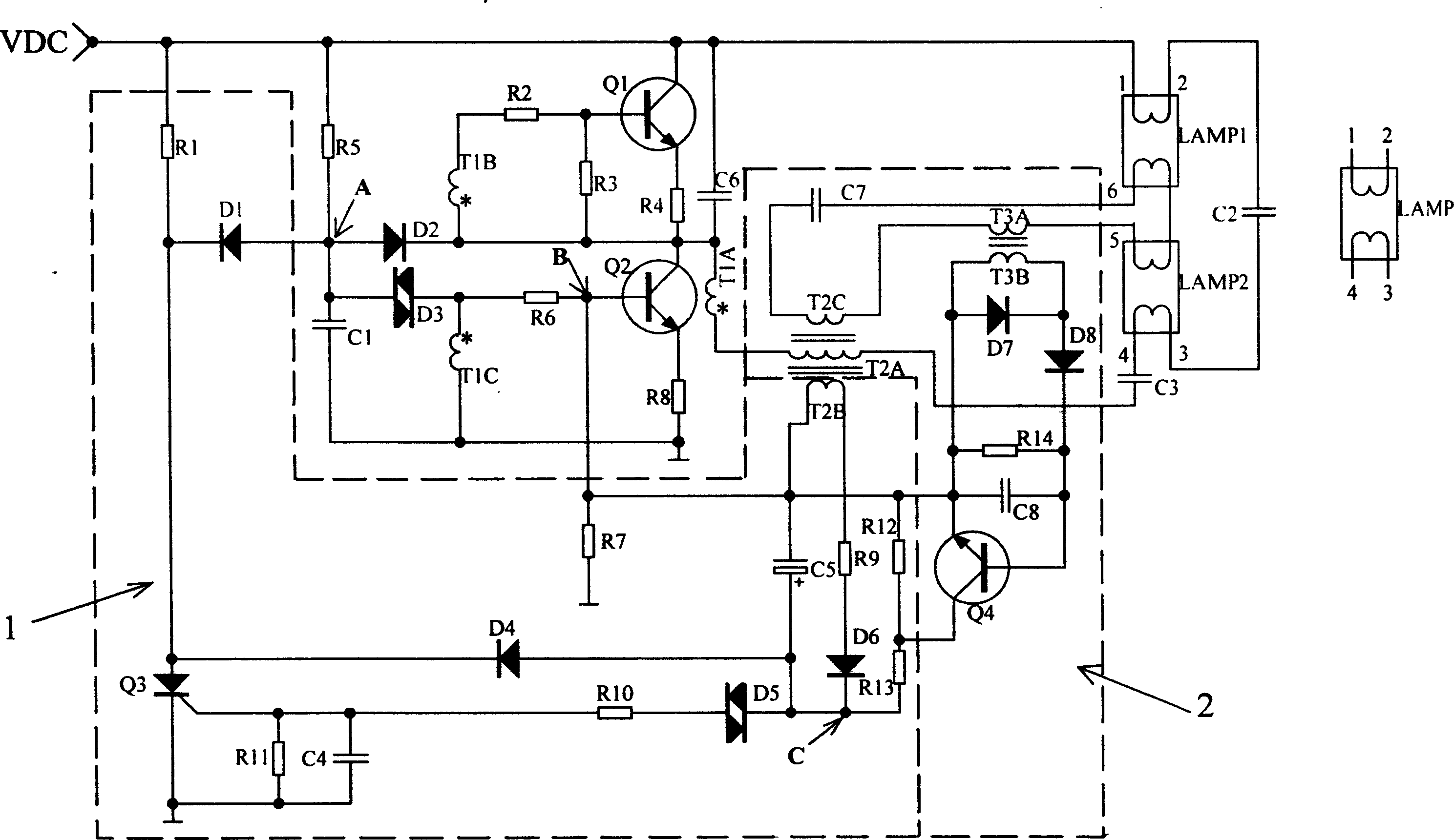
[0035] see image 3 , the upper part of the virtual frame is a typical DC / AC converter circuit, the right side is the lamp output circuit, and the positive feedback abnormal protection circuit of the present invention is inside the virtual frame, wherein: the basic protection circuit is in the virtual frame 1, and the basic protection circuit is in the virtual frame 2 It is a load single and double lamp detection control circuit.

[0036] 1. Basic protection circuit part

[0037] Power supply resistance R 1 One end of the DC power supply V DC , and the other end is respectively co...


PUM


Abstract

The disclosed positive feedback abnormal protective circuit for electronic ballast of a fluorescent lamp comprises a first secondary winding T2B of output inductance to connect to control end of an abnormal protective actuator Q3 through a limit and rectification circuit and filter circuit. Wherein, the Q3 control DC / DC converter to stop oscillating for abnormal condition. This invention can improve reliability without adding cost or complexity.

Description

technical field [0001] The invention relates to abnormality protection technology in power electronics and lighting electronics, in particular to the abnormality protection technology of electronic ballasts for fluorescent lamps. Background technique [0002] In the existing application technology of electronic ballasts for fluorescent lamps, they are generally composed of a rectifier circuit, a DC / AC converter, an output circuit and a fluorescent tube circuit. In order to reduce product size and reduce product cost, its DC / AC part usually adopts a self-excited half-bridge oscillator circuit mode composed of bipolar crystals, and some abnormal protection is added between the DC / AC converter and the output circuit. circuit to ensure that the electronic ballast will not be damaged when the fluorescent tube is abnormal, so as to improve the reliability of the product (see figure 1 ). [0003] The abnormal protection circuit in the prior art is generally a current sampling cir...

Claims


Application Information

Patent Timeline
IPC IPC(8): H05B41/285H05B41/298
Inventor 曾浩然
Owner DONGYANG TOSPO LIGHTING
Learn More