Seat belt automatic retractor with free wheel clutch

A technology of automatic retractable device and seat belt, which is applied in the direction of car seat belt, belt tightener, transportation and packaging, etc., to achieve the effect of reducing production cost

Inactive Publication Date: 2011-12-14
HUGO KERN & LIEBERS & PLATINEN & FEDERNFAB
View PDF4 Cites 0 Cited by
  • Summary
  • Abstract
  • Description
  • Claims
  • Application Information

AI Technical Summary

Problems solved by technology

[0006] Another disadvantage of the known automatic retractor for seat belts is that the slipping clutch with the wire spring is not reliable enough, it should still work despite exceeding the operating range of the balance spring. Shaft can be rotated in winding direction

Method used


Image

  • Seat belt automatic retractor with free wheel clutch
  • Seat belt automatic retractor with free wheel clutch
  • Seat belt automatic retractor with free wheel clutch

Examples


Embodiment Construction

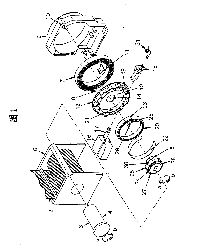
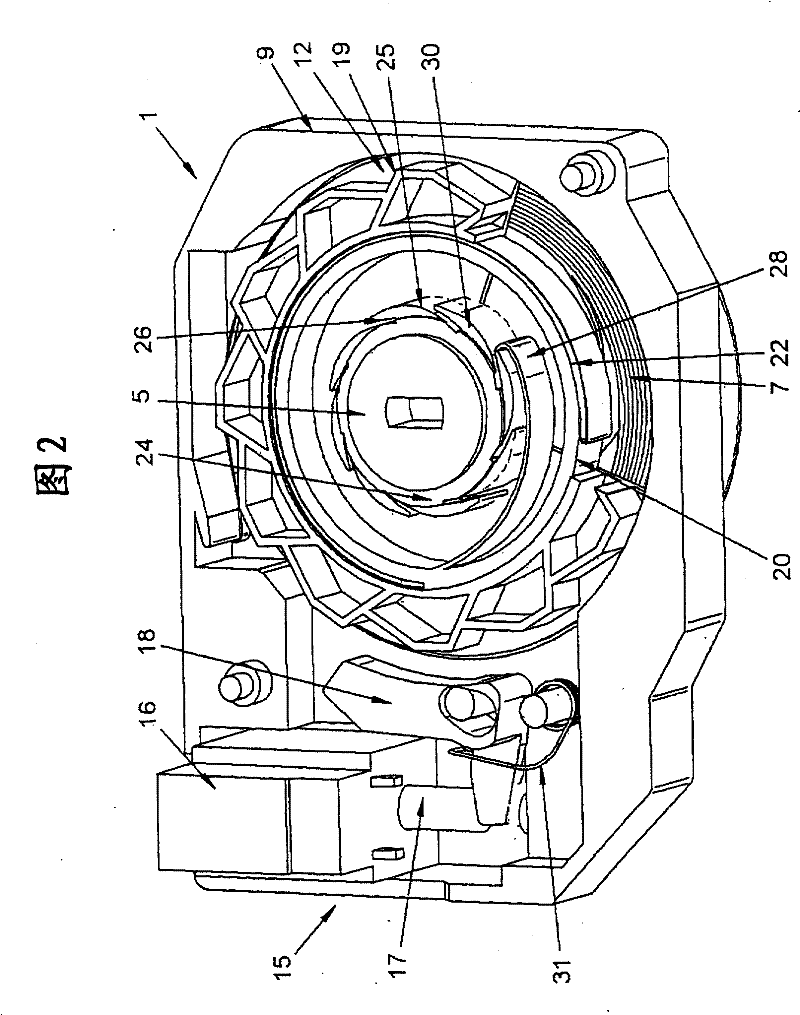
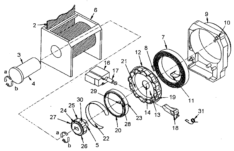
[0027] Shown among the figure is a safety belt automatic telescoping device 1. The belt retractor 1 can be used to wind the belt 2 onto the belt take-up section 3 of the shaft 4 . The shaft 4 consists of two parts and the parts comprise the belt take-up section 3 and the drive section 5 . The shaft 4 is rotatably housed in a metal casing 6 .

[0028] In addition, the seat belt automatic retractor 1 includes a main drive spring 7 which is fixedly connected to its outer end 8 with a plastic housing 9 . The plastic housing 9 is connected laterally to the metal housing 6 by means of three pins 10 .

[0029] The main drive spring 7 connects its inner end 11 in a rotationally fixed manner to the drive section 5 of the shaft 4 . The shaft 4 is thus pretensioned by the main drive spring 7 in the winding direction a when the shaft 4 is rotated in the unwinding direction b, ie when the seat belt 2 is unrolled.

[0030] Furthermore, the automatic seat belt retractor 1 also includes a...


PUM


Abstract

The invention relates to an automatic telescoping device (1) for a safety belt, comprising a shaft (4), a main drive spring arranged so that the shaft (4) is pre-tensioned along a winding direction (a) of the safety belt (2) (7), a ratchet (12) rotatably arranged relative to the shaft (4), a locking device (15) for locking the rotational movement of the ratchet (12) in the winding direction (a) and a Balance spring, the balance spring is arranged so that when the ratchet (12) is locked, it can transmit a pretension force acting against the direction of the pretension force of the main drive spring (7) to the shaft (4), the characteristic of the present invention There is provided a freewheel coupling which, on the one hand, enables a force transmission from the shaft to the balance spring in the winding direction (a) when the ratchet is locked, and on the other hand allows the balance spring to move when the ratchet is not locked. A clutch segment performs relative rotational movement relative to the shaft in the winding direction (a).

Description

technical field [0001] The invention relates to an automatic telescoping device for a safety belt. Background technique [0002] Such an automatic belt retractor is known from EP 1 157 905 B1. In the known automatic belt retractor, a main drive spring is provided which pretensions a shaft with a belt winding section in the winding direction. In addition, a balancing spring is provided which is arranged to act against the direction of the main drive spring. The balance spring has its outer end fixedly connected to the ratchet on the one hand and its inner end to the ring of the slipping clutch on the other hand. The ratchet can be locked in the winding direction by means of a locking device. [0003] It is desirable that the winding torque exerted by the main drive spring on the axle be reduced when the seat belt is fastened. This reduced torque is created in such a way that as soon as the seat belt buckle is engaged, the ratchet is locked in the winding direction by mea...

Claims


Application Information

Patent Timeline
Patent Type & Authority Patents(China)
IPC IPC(8): B60R22/44
CPCB60R2022/4433B60R22/44B60R22/405B60R22/4619B60R2022/468
Inventor M·本纳
Owner HUGO KERN & LIEBERS & PLATINEN & FEDERNFAB
Why Eureka
Try Eureka