Line ice-melting method for extra-high voltage DC electric transmission system

A technology for UHV DC and power transmission systems, which is used in cable installation, electrical components, overhead installation, etc., and can solve problems such as fewer wires, communication interruptions, and long-term power outages.

Inactive Publication Date: 2006-10-18
STATE GRID CORP OF CHINA
View PDF0 Cites 21 Cited by
  • Summary
  • Abstract
  • Description
  • Claims
  • Application Information

AI Technical Summary

Problems solved by technology

[0003] In our country, there are few studies on the problem of icing on conductors. In the survey and design of power transmission lines, the scope and thickness of icing are expanded due to insufficient evidence, resulting in unnecessary huge waste; Insufficient ice design leads to frequent and severe icing accidents on power lines
When an ice damage accident occurs on the line, the we...

Method used


Image

  • Line ice-melting method for extra-high voltage DC electric transmission system
  • Line ice-melting method for extra-high voltage DC electric transmission system
  • Line ice-melting method for extra-high voltage DC electric transmission system

Examples


Embodiment 1

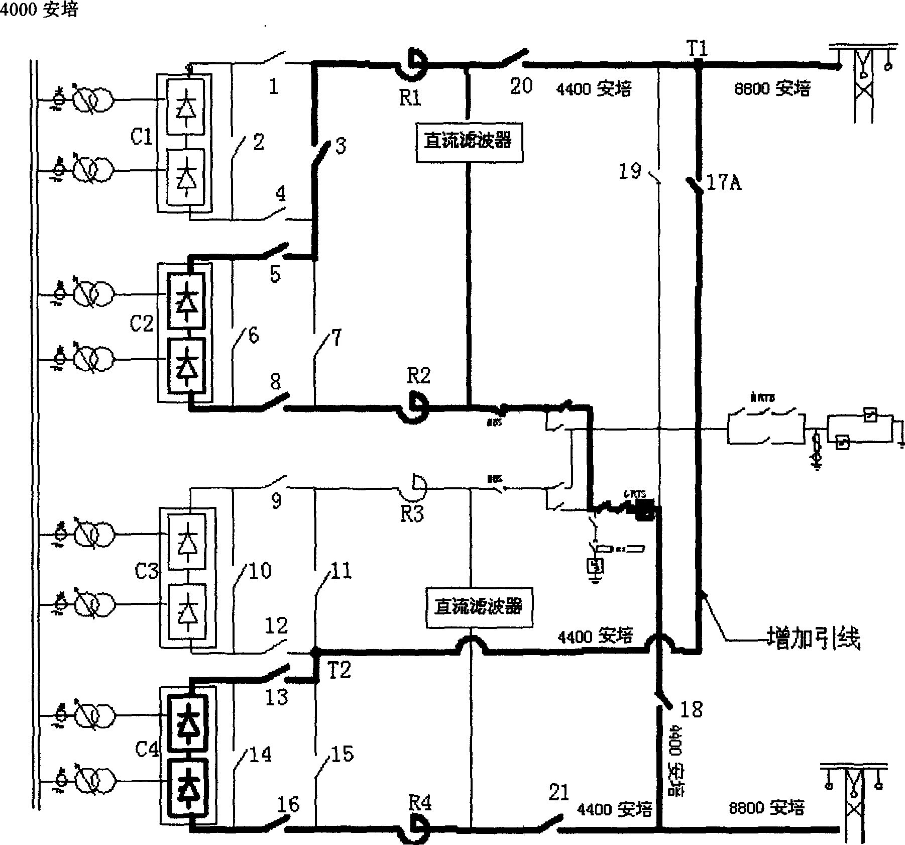
[0018] Example 1: Two inverters with two poles

[0019] figure 2 It shows the parallel connection diagram of two DC deicing bipolar converters. This wiring diagram can use any converter of one pole and the high-end converter (C1 or C4) of the other pole to form a parallel connection. A high-side converter is necessary because the low-voltage side of the converter needs to withstand voltages of opposite polarity in a parallel connection. Take converters C2 and C4 as an example, such as figure 2 As shown, a connection line is added at the low voltage end of C4 to the outside of the line isolation switch 20 of the other pole, that is, the connection line between T1 and T2. If an isolating switch 17A is added on the connection line, online melting of ice can be realized. The process is as follows: first close the switches 20, 3, 5, 8, and 18, turn the converter C2 into the metal loop operation mode, close the switches 17A, 13, 16, and 21, so that the converter C4 is connected...

Embodiment 2

[0020] Example 2: Two converters of the same pole are connected in parallel

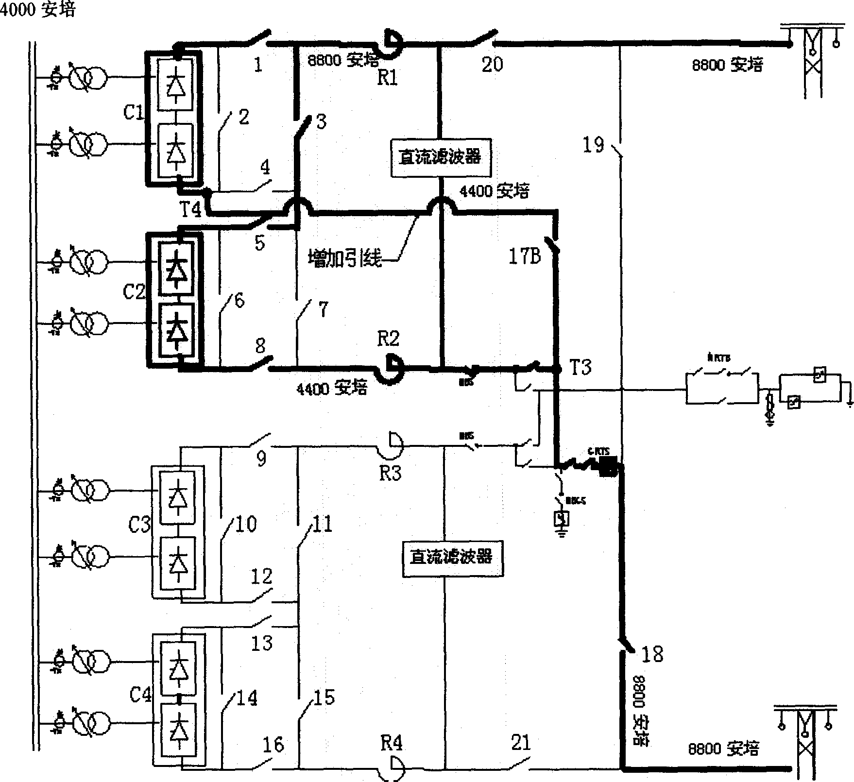
[0021] image 3 It is the wiring diagram of parallel connection of two converters of DC ice-melting single pole, in which two converters of the same pole are connected in parallel, that is, converters C1 and C2 in the figure, or converters C3 and C4; The terminal converter station adopts the same wiring.

[0022] Taking converters C1 and C2 as an example, a connection line is added from the low-voltage end of converter C1 to the DC neutral line, that is, the connection line between T3 and T4. At the same time, an isolating switch 17B is added on the connection line between T1 and T2, and this solution can realize ice melting without power failure. First close the switches 20, 3, 5, 8, and 18, and the converter station is converted to the single-pole single-converter C2 metal loop operation, and then close the isolation switches 1 and 17B to start the high-end converter and increase the current . ...


PUM


Abstract

A method for melting ice on line of super high voltage DC transmission system adds connection wire and switch in main wiring of super high voltage DC transverting station to change connection relation between transverters and to raise current on transmission line for melting ice on transmission line by changing on-off state of switch correspondingly.

Description

technical field [0001] The present invention relates to a method for melting ice of a UHV DC transmission system. More specifically, the present invention combines the characteristics of four converters in each UHV DC converter station by studying the ice melting current required by the line , which relates to a technical solution for a line melting method for an UHVDC power transmission system. Background technique [0002] ice area Xiangjiaba—Shanghai (km) Xiluodu - Zhuzhou (km) Xiluodu - West Zhejiang (km) 10mm ice zone 1470 468 1184 15mm ice zone 407 301 331 20mm ice area 120 139 160 30mm ice zone 56 52 46 50mm ice zone 13 10 7 total 2066 970 1728 [0003] In our country, there are few studies on the problem of icing on conductors. In the survey and design of p...

Claims


Application Information

Patent Timeline
IPC IPC(8): H02G7/16
Inventor 刘振亚刘泽洪袁清云高理迎
Owner STATE GRID CORP OF CHINA
Why Eureka
Try Eureka