Ballast

A ballast and circuit technology, applied in the direction of lighting devices, light sources, electrical components, etc., can solve the problems of high power consumption, low power factor, large investment in initial installation, etc., and achieve low power consumption, improved light efficiency, and multiple models Effect

Inactive Publication Date: 2006-10-18
卢甘
View PDF0 Cites 6 Cited by
  • Summary
  • Abstract
  • Description
  • Claims
  • Application Information

AI Technical Summary

Problems solved by technology

[0004] The invention overcomes the shortcomings of the existing magnetic ballasts, such as large power consumption, low power factor, and large initial investment, and provides a green, energy-saving, intelligent, and multi-functional electronic ballast

Method used


Image

  • Ballast
  • Ballast
  • Ballast

Examples


Embodiment Construction

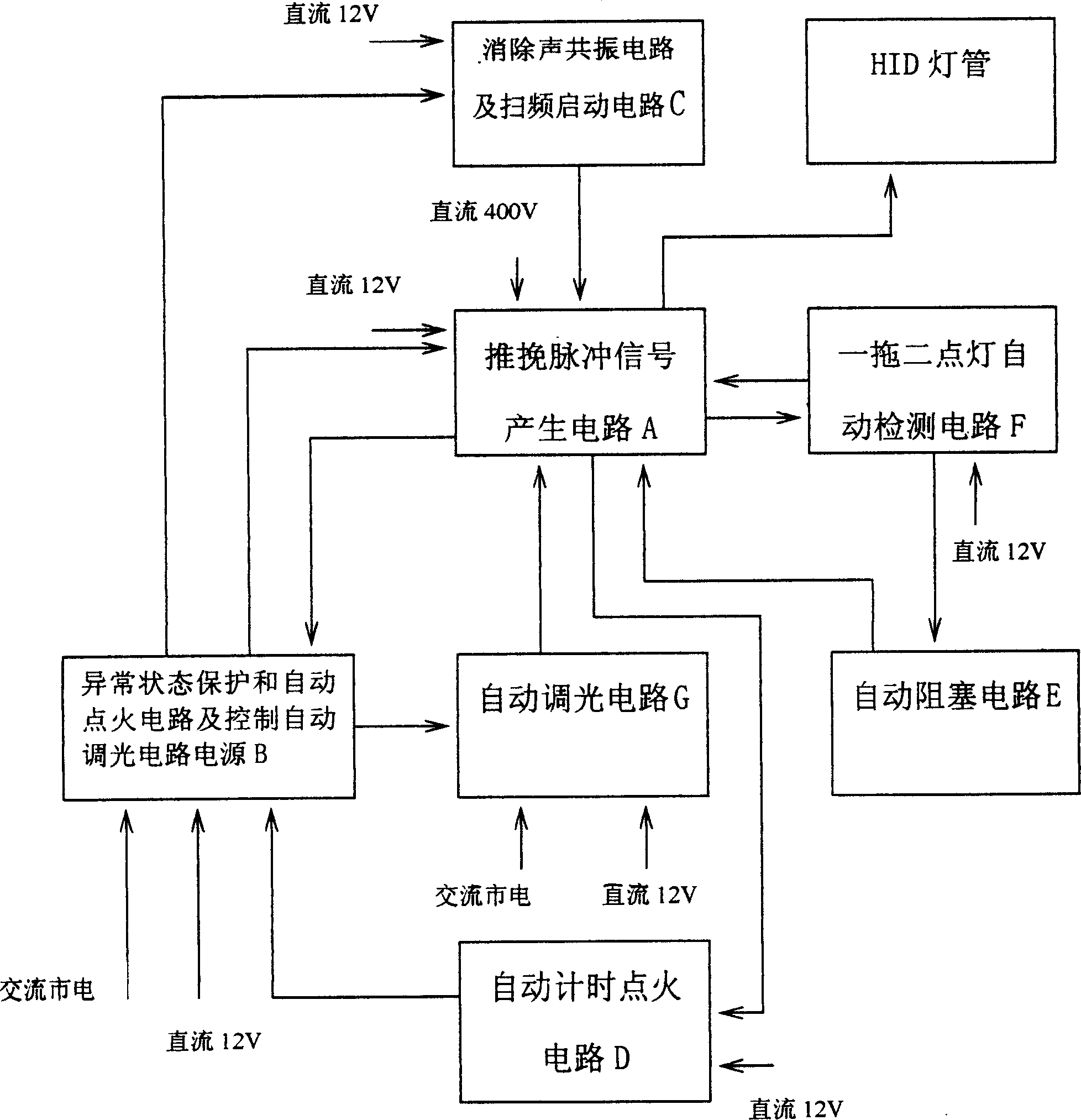
[0032] Below in conjunction with accompanying drawing and specific embodiment the present invention is described in further detail:

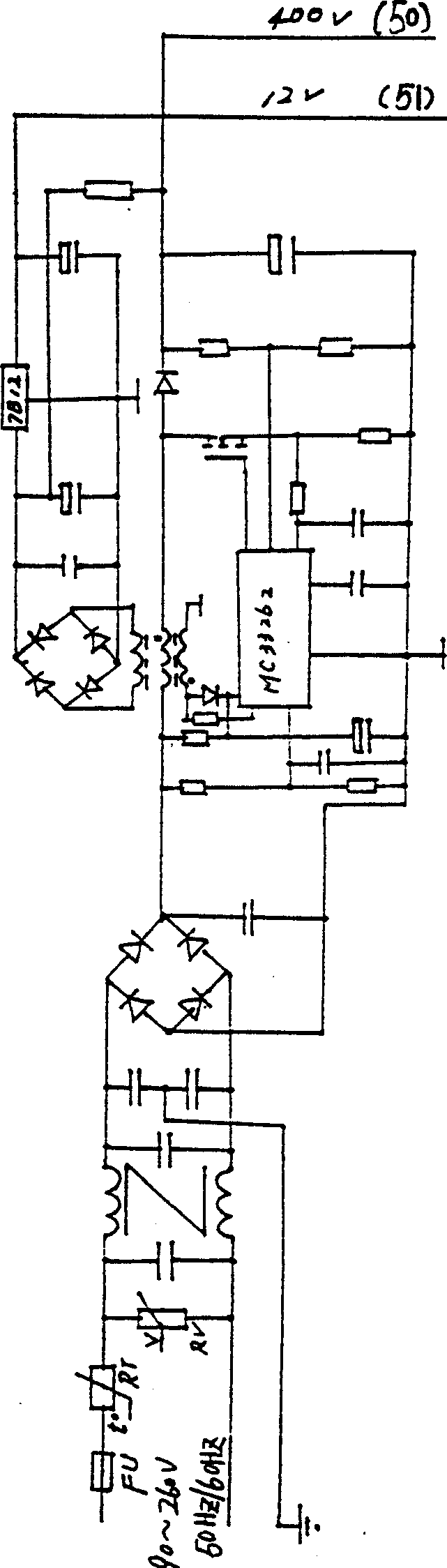
[0033] A ballast, comprising a push-pull pulse signal generating circuit A and a power supply circuit H;

[0034] One of the power circuit H generates a DC 12V power supply to each control circuit, and the other generates a DC 400V power supply to the high-frequency conversion circuit of the push-pull pulse signal generation circuit A;

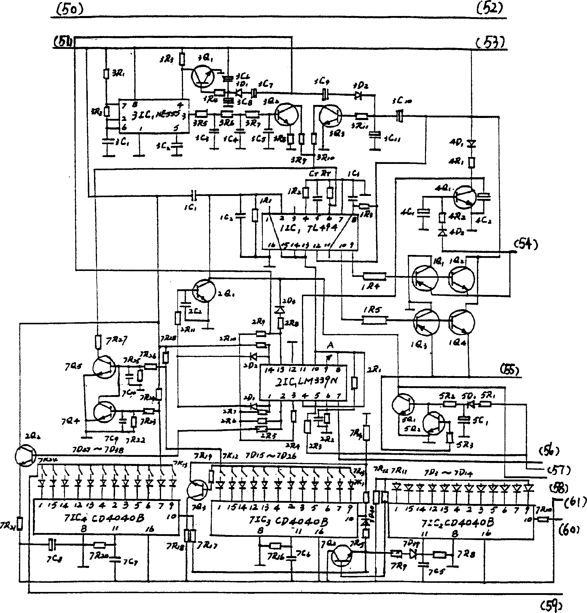
[0035] The push-pull pulse signal generating circuit A generates push-pull pulse signals of different frequencies, which are converted by a high-frequency circuit and supplied to high-intensity gas discharge lamps of different powers.

[0036] The present invention also includes abnormal state protection and automatic ignition circuit and control automatic dimming circuit power supply B, noise elimination resonance circuit, frequency scanning start ignition circuit C, automatic timing ignition circuit D, automat...


PUM


Abstract

An electronic ballast consists of signal generating circuit of push-pull pulse, abnormal state protection and automatic ignition circuit, power supply of controlled automatic regulation circuit, circuit for eliminating sound resonance, ignition circuit of sweep frequency stark-up, automatic block circuit, automatic detection circuit of one to two lighting on mode and light automatic regulation circuit.

Description

【Technical field】 [0001] The invention relates to a ballast, in particular to an electronic ballast for a high-intensity gas discharge lamp. 【Background technique】 [0002] In recent years, the contradiction between my country's electricity supply and demand has become more and more tense. In addition to the improvement of the living standards of urban and rural people in our country, the large purchase of household appliances and the rapid development of industry, agriculture and commerce have greatly increased the use of electricity, and the electricity consumption of road lighting in my country has also increased significantly. Among them, high-intensity gas discharge lamps represented by high-pressure sodium lamps and metal halide lamps have always used inductive ballasts. Their disadvantages are: high power consumption, low power factor, and large investment in initial equipment. These shortcomings are all related to the high development of science and technology. Today a...

Claims


Application Information

Patent Timeline
IPC IPC(8): H05B41/288H05B41/292
CPCY02B20/00
Inventor 卢甘
Owner 卢甘
Why Eureka
Try Eureka