Gas storage tank with gas-liquid separating function
A gas-liquid separation and gas storage tank technology, which is applied in gas/liquid distribution and storage, fixed-capacity gas storage tanks, pressure vessels, etc., can solve the problems of increasing user cost, unsatisfactory oil-water separation effect, and high price of oil-water separators. problem, to achieve the effect of improving the effect
- Summary
- Abstract
- Description
- Claims
- Application Information
AI Technical Summary
Problems solved by technology
Method used
Image

Examples
Embodiment 1
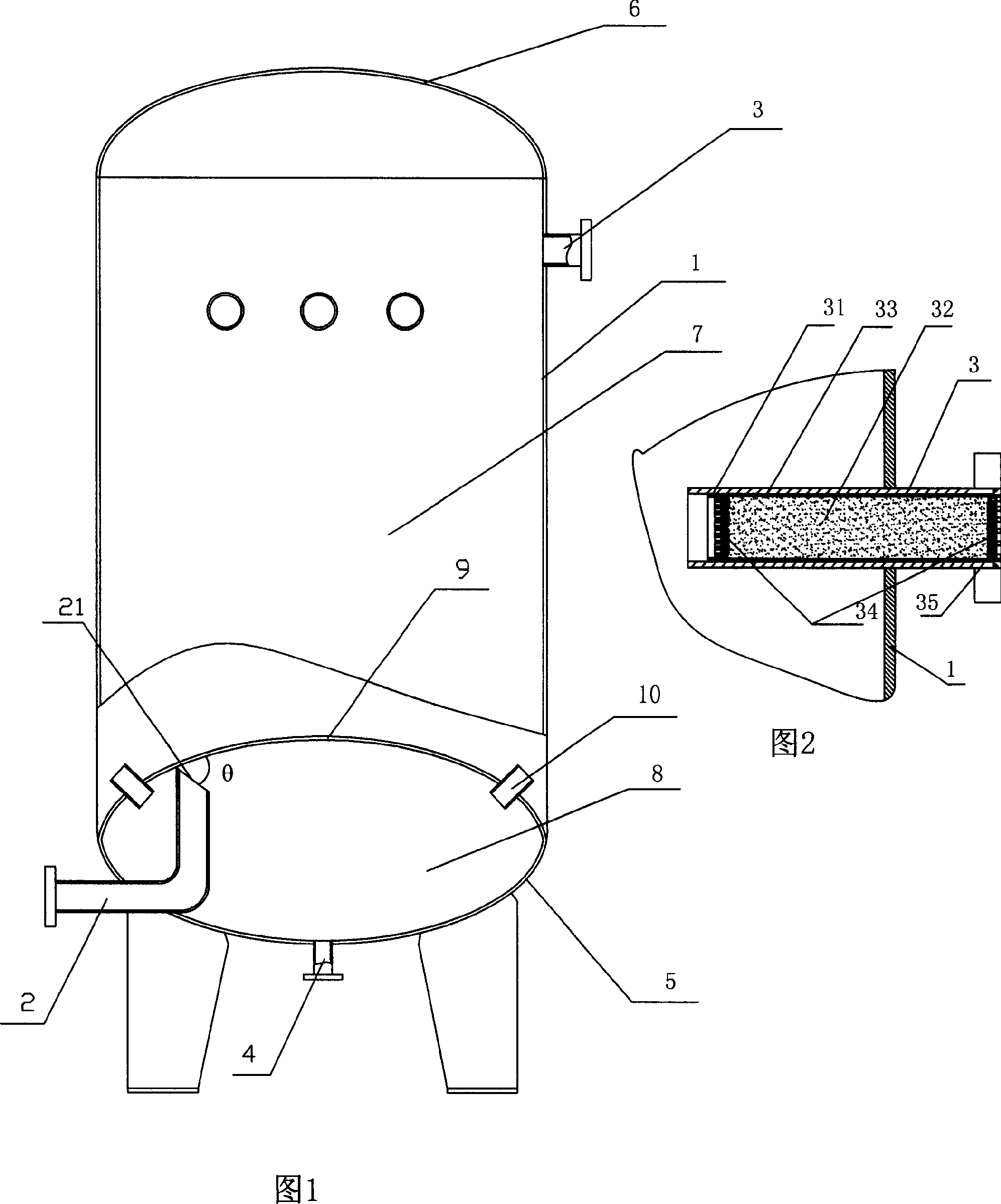
[0020] Embodiment 1: A gas storage tank with gas-liquid separation function, having a cylinder body 1 with a cylindrical structure, an air inlet pipe 2, an air outlet pipe 3, a drainer 4, a lower head 5, an upper head 6, and the body 1 is provided with an inner head 9, the inner head 9 is a spherical structure, opposite to the direction in which the lower head 5 protrudes, and the connection point between the inner head 9 and the inner wall of the cylinder body 1 is located There is a gap at 3 cm above the connection, so that the inner head 9 divides the air storage tank into an air intake area 8 and an air storage area 7; the air intake pipe 2 extends into the air intake area 8 from the lower end head 5, and The nozzle 21 of the gas outlet is close to the inner head 9, and the distance between the upper edge of the nozzle 21 and the lower wall of the inner head 9 is 1 cm. The acute angle θ formed by the outer tangent lines of the intersection points is 30 degrees; four air ou...
Embodiment 2
[0021] Embodiment 2: A gas storage tank with gas-liquid separation function, having a cylinder body 1 with a cylindrical structure, an air inlet pipe 2, an air outlet pipe 3, a drainer 4, a lower head 5, an upper head 6, and the body 1 is provided with an inner head 9, the inner head 9 is a spherical structure, and the direction in which the lower head 5 protrudes is opposite, and the connection point between the inner head 9 and the inner wall of the cylinder body 1 is at the junction of the cylinder body and the lower head There is a gap at 3 cm below, so that the inner head 9 divides the air storage tank into an air intake area 8 and an air storage area 7, and the air intake pipe 2 is stretched into the air intake area 8 by the lower end head 5. The nozzle 21 is close to the inner head 9, and the distance between the upper edge of the nozzle 21 and the lower wall 9 of the inner head is 0.5cm. The acute angle θ formed by the outer tangent is 15 degrees. An air outlet pipe 10...
Embodiment 3
[0022] Embodiment 3: A gas storage tank with gas-liquid separation function, having a cylinder body 1 with a cylindrical structure, an air inlet pipe 2, an air outlet pipe 3, a drainer 4, a lower head 5, an upper head 6, and the body 1 is provided with an inner head 9, the inner head 9 is a spherical structure, opposite to the direction in which the lower head 5 protrudes, and the connection point between the inner head 9 and the inner wall of the cylinder body 1 is at the joint between the cylinder body 1 and the lower head 5 There is a gap at 2 cm below the connection, so that the inner head 9 divides the air storage tank into an air intake area 8 and an air storage area 7, and the air intake pipe 2 is stretched into the air intake area 8 by the lower end head 5. The nozzle 21 of the gas outlet is close to the inner head 9, the distance between the upper edge of the nozzle 21 and the lower wall of the inner head 9 is 2cm, the nozzle 21 is an oblique section, and the extension...
PUM
 Abstract
Description
Claims
Application Information
 - R&D
- Intellectual Property
- Life Sciences
- Materials
- Tech Scout
- Unparalleled Data Quality
- Higher Quality Content
- 60% Fewer Hallucinations
Browse by: Latest US Patents, China's latest patents, Technical Efficacy Thesaurus, Application Domain, Technology Topic, Popular Technical Reports.
© 2025 PatSnap. All rights reserved.Legal|Privacy policy|Modern Slavery Act Transparency Statement|Sitemap|About US| Contact US: help@patsnap.com